Induction hardening apparatus, induction hardening method, induction heating coil, heat treatment apparatus, and heat treatment method

a technology hardening method, which is applied in the direction of heat treatment apparatus, electric/magnetic/electromagnetic heating, furnaces, etc., can solve the problems of complex shape or condition setting of induction heating coil, high-output power is required, and the inability to realize the apparatus

Active Publication Date: 2012-05-24
NETUREN CO LTD
View PDF5 Cites 14 Cited by
  • Summary
  • Abstract
  • Description
  • Claims
  • Application Information

AI Technical Summary

Problems solved by technology

The technology of the induction heating has the following problems.
That is, in the induction hardening apparatus adopting the single shot heating process, since the induction heating coil associated with a size or a shape of the treatment target portion must be used, for example, when the treatment target portion has a complicated shape, a shape or condition setting of the induction heating coil becomes complicated, and realizing the apparatus is impossible.
Furthermore, when the treatment target portion is large, and a big induction heating coil is required, this results in a problem that high-output power is required.
Moreover, when the treatment object is deformed due to, e.g., thermal expansion at the time of induction heating, maintaining an appropriate dimension between the induction heating coil and the treatment object is difficult.
Therefore, the induction heating coil must be set to have a larger size in advance, and hence a problem of poor heating efficiency occurs.
On the other hand, in the scanning heat treatment method, when the induction heating coil is formed into a shape associated with a part of the treatment target portion, a treatment area per unit time is small, a treatment time is increased, and treatment efficiency is deteriorated.
Additionally, in the case of moving the induction heating coil while continuously performing the heat treatment and the cooling treatment, for example, when an annular treatment target portion is to be treated, there occurs a problem of generation of a soft zone, which means the necessary hardness cannot be obtained at a boundary between a start portion and an end portion of the treatment.

Method used


Image

  • Induction hardening apparatus, induction hardening method, induction heating coil, heat treatment apparatus, and heat treatment method
  • Induction hardening apparatus, induction hardening method, induction heating coil, heat treatment apparatus, and heat treatment method
  • Induction hardening apparatus, induction hardening method, induction heating coil, heat treatment apparatus, and heat treatment method

Examples


first embodiment

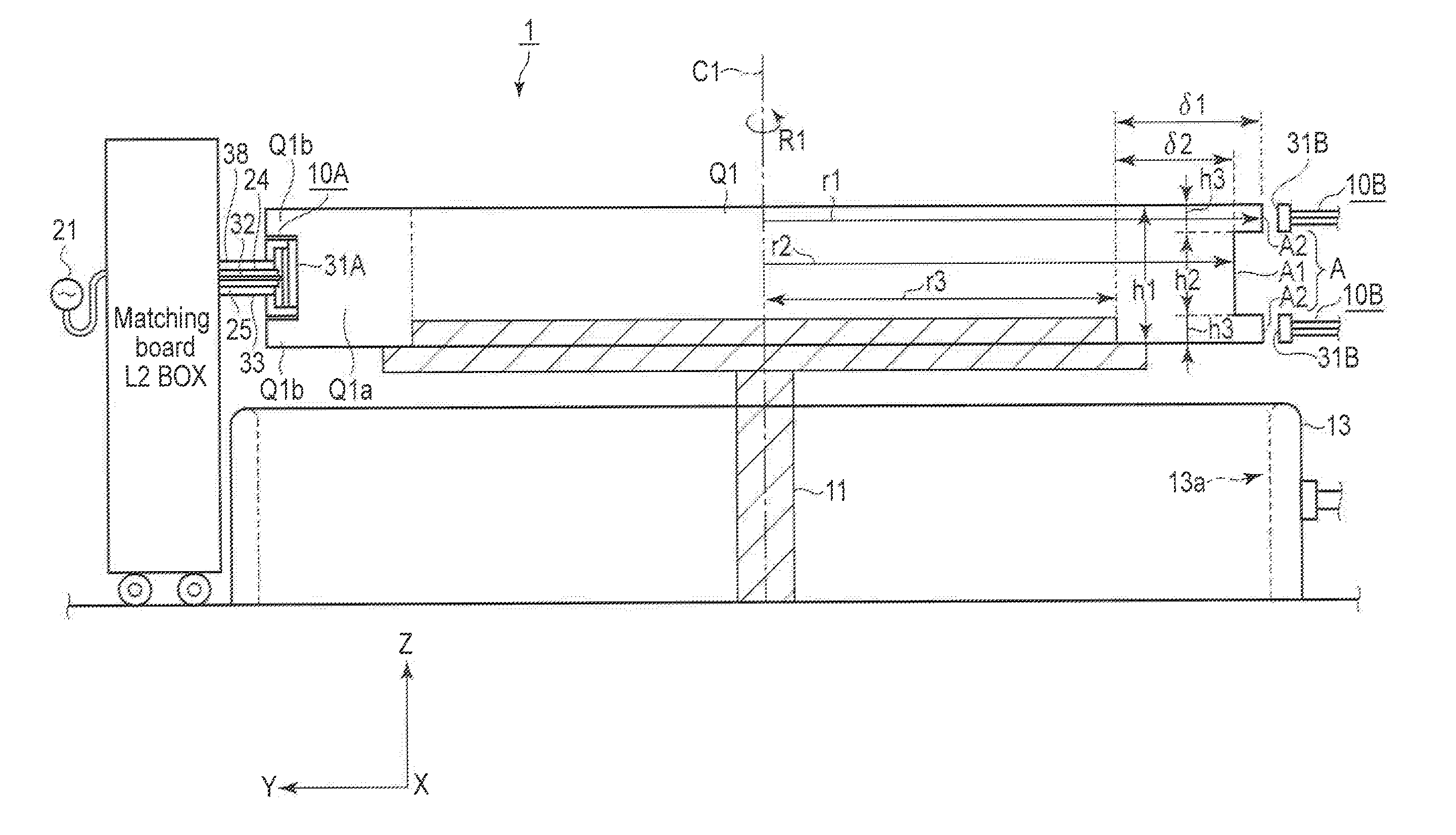
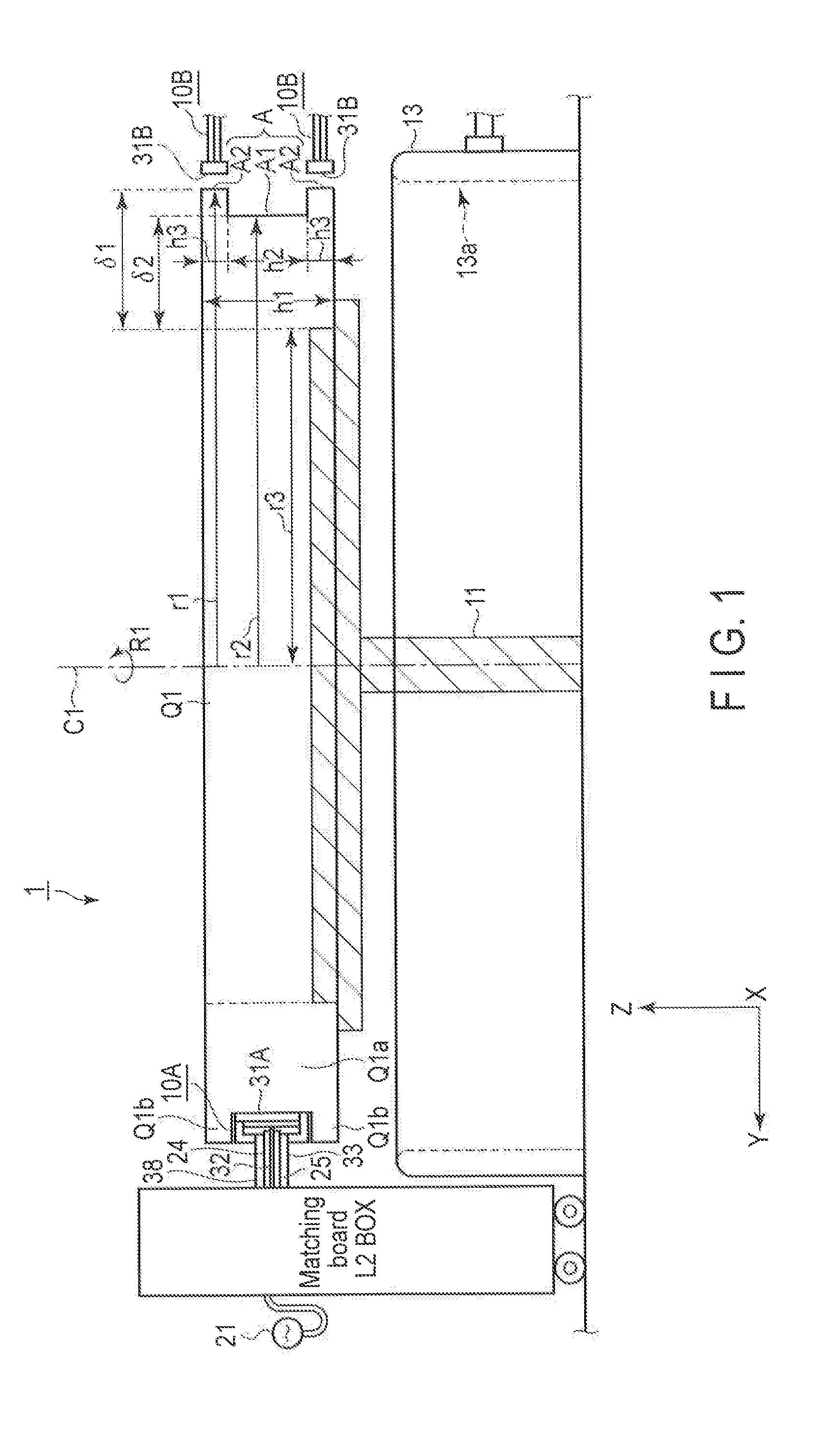
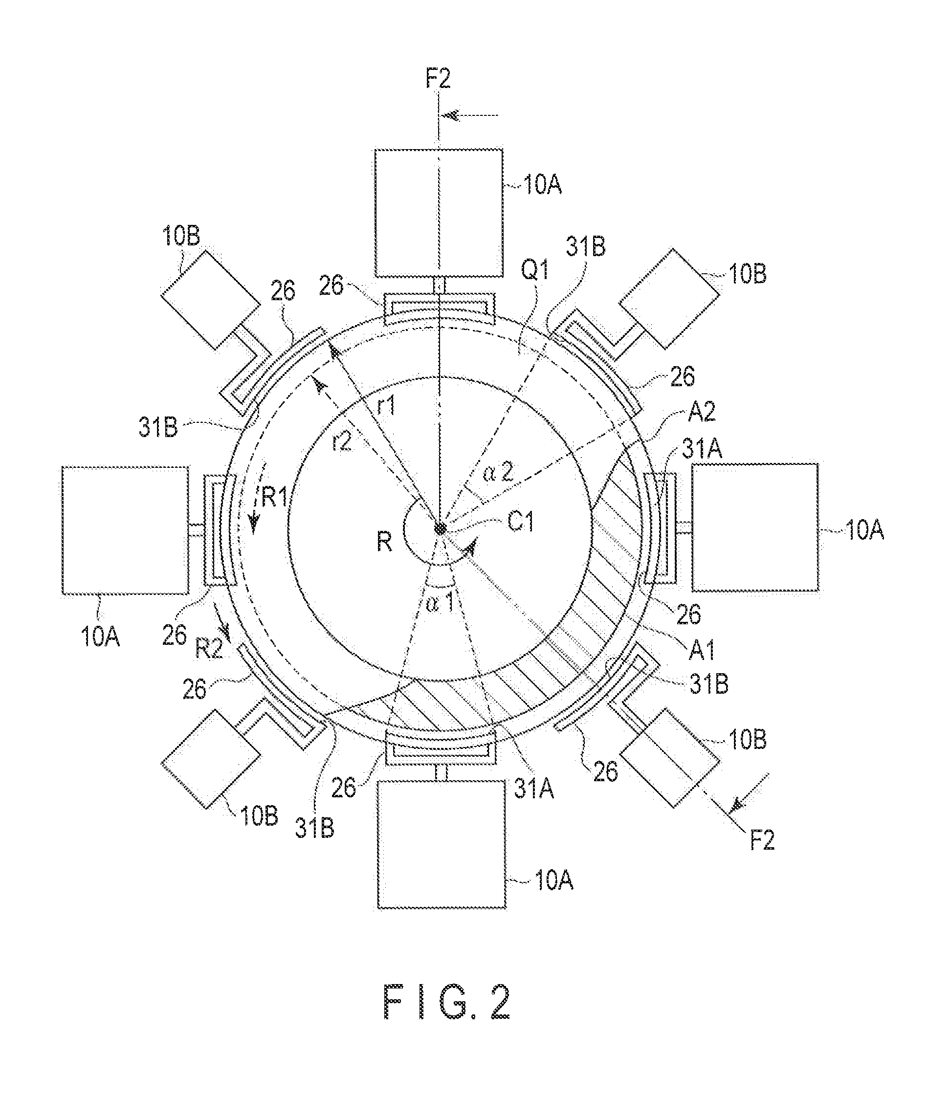
[0059]An induction hardening apparatus and an induction hardening method according to a first embodiment of the present invention will now be described hereinafter with reference to FIG. 1 to FIG. 9, FIG. 1 is a cross-sectional view showing a configuration of an induction hardening apparatus 1 according to this embodiment, and FIG. 2 is a plan view. As shown in FIG. 1 and FIG. 2, the induction hardening apparatus 1 comprises a movement support unit (moving unit) that movably supports a workpiece Q1 as a treatment object, respective heating devices 10A and 10B arranged on the outer circumference of the workpiece Q1, and cooling unit 13 (cooling unit) that cools the workpiece Q1 after a heating treatment step for the workplace Q1. The cooling unit 13 provided on the lower side is formed into a cylindrical shape to surround the outer side of the workpiece Q1 that has moved to the lower side after the heating treatment, and it cools the workpiece Q1 arranged in an inner space 13a.

[0060...

second embodiment

[0088]An induction hardening apparatus 2 according to a second embodiment of the present invention will now be described with reference to FIG. 10 and FIG. 11. It is to be noted that elements other than shapes of a workpiece Q2 and a heating conductor portion 31 are equal to those in the first embodiment to omit a repeated explanation. It is to be noted that the workpiece Q2 has a cylindrical shape having an annular plane portion.

[0089]FIG. 10 is a plan view showing en arrangement of the induction hardening apparatus 2 according to this embodiment, and FIG. 11 is en explanatory view showing a shape of the heating conductor portion 31 in the induction hardening apparatus 2.

[0090]In this embodiment, as shown in FIG. 10, each of upper and lower end surfaces of the workpiece Q2 has a planar cylindrical shape, and each end surface is determined as a treatment target portion A. Further, the heating conductor portion 31 of a first heating device 10A is formed into a zigzag shape such that ...

third embodiment

[0095]An induction hardening apparatus 2 according to a third embodiment of the present invention will now be described with reference to FIG. 12. It is to be noted that structures are equal to those in the foregoing embodiments except that a shape of a workpiece Q3 is different and a heating conductor portion 31 is parallel to an inclined surface of the workplace Q3, thereby omitting a repeated explanation.

[0096]Since a plan view of the induction hardening apparatus 2 is equal to FIG. 10 and a plan view of the heating conductor portion 31 is equal to FIG. 11, these views will be omitted.

[0097]In this embodiment, as shown in FIG. 12, the workpiece Q3 has a drum-like shape such that upper and lower outer peripheral surfaces are inclined, and the outer peripheral surfaces are determined as a treatment target portion A. The inclined upper outer peripheral surface of the workpiece Q3 is determined as a first region A1, and the inclined lower outer peripheral surface is determined as a s...


PUM

PropertyMeasurementUnit
center angleaaaaaaaaaa
poweraaaaaaaaaa
speedaaaaaaaaaa

Abstract

According to an embodiment, an induction heating coil includes a heating conductor portion which is formed of a conductor member and has a zigzag shape in which a bent portion opened to one side in a first direction and a bent portion opened to the other side in the first direction are alternately continuously arranged in opposite directions along a second direction crossing the first direction.

Description

CROSS REFERENCE TO RELATED APPLICATIONS[0001]This application is a Continuation Application of PCT Application No. POT / JP2010 / 062847, filed. Jul. 29, 2010 and based upon and claiming the benefit of priority from prior Japanese Patent Applications No. 2009-178256, filed Jul. 30, 2009; No. 2010-121901, filed May 27, 2010; No. 2010-150411, filed Jun. 30, 2010; and No. 2010-157556, filed Jul. 12, 2010, the entire contents of all of which are incorporated herein by reference.BACKGROUND OF THE INVENTION[0002]1. Field of the Invention[0003]The present invention relates to an induction hardening apparatus, an induction hardening method, an induction heating coil, a heat treatment apparatus, and a heat treatment method, and more particularly to a technology for improving heat treatment efficiency and performing a uniform treatment.[0004]2. Description of the Related Art[0005]In an induction hardening method for performing a heat treatment such as high-frequency hardening with respect to a me...

Claims


Application Information

Patent Timeline
Patent Type & Authority Applications(United States)
IPC IPC(8): H05B6/10
CPCC21D1/10C21D1/42H05B6/36C21D2221/00H05B6/102C21D9/40Y02P10/25H05B6/10H05B6/40H05B6/44
Inventor TANAKA, YOSHIMASAMISAKA, YOSHITAKAASANO, YUJI
Owner NETUREN CO LTD
Why Eureka
Try Eureka