Heating cartridge with coupling element

a technology of coupling element and heating cartridge, which is applied in the field of heating cartridge, can solve the problems of not being able to avoid, occupying a large space in the holder, and not being able to meet the needs of some applications, so as to optimize the possibilities of application and use of the heating cartridge, and the effect of reducing the spa

Active Publication Date: 2008-11-27
TUERK & HILLINGER
View PDF25 Cites 15 Cited by
  • Summary
  • Abstract
  • Description
  • Claims
  • Application Information

AI Technical Summary

Benefits of technology

[0006]The basic object of the present invention is to provide a heating cartridge of the type mentioned in the introduction in an easy-to-carry-out manner with a holder, which is preferably combined with a connector

Problems solved by technology

Aside from the fact that the extrusion coating of the flange leads to a larger outside diameter of the holder in this area, it cannot be avoided that a part of the metal sheathing must be extrusion coated as well.
This means that the holde

Method used


Image

  • Heating cartridge with coupling element
  • Heating cartridge with coupling element
  • Heating cartridge with coupling element

Examples


Embodiment Construction

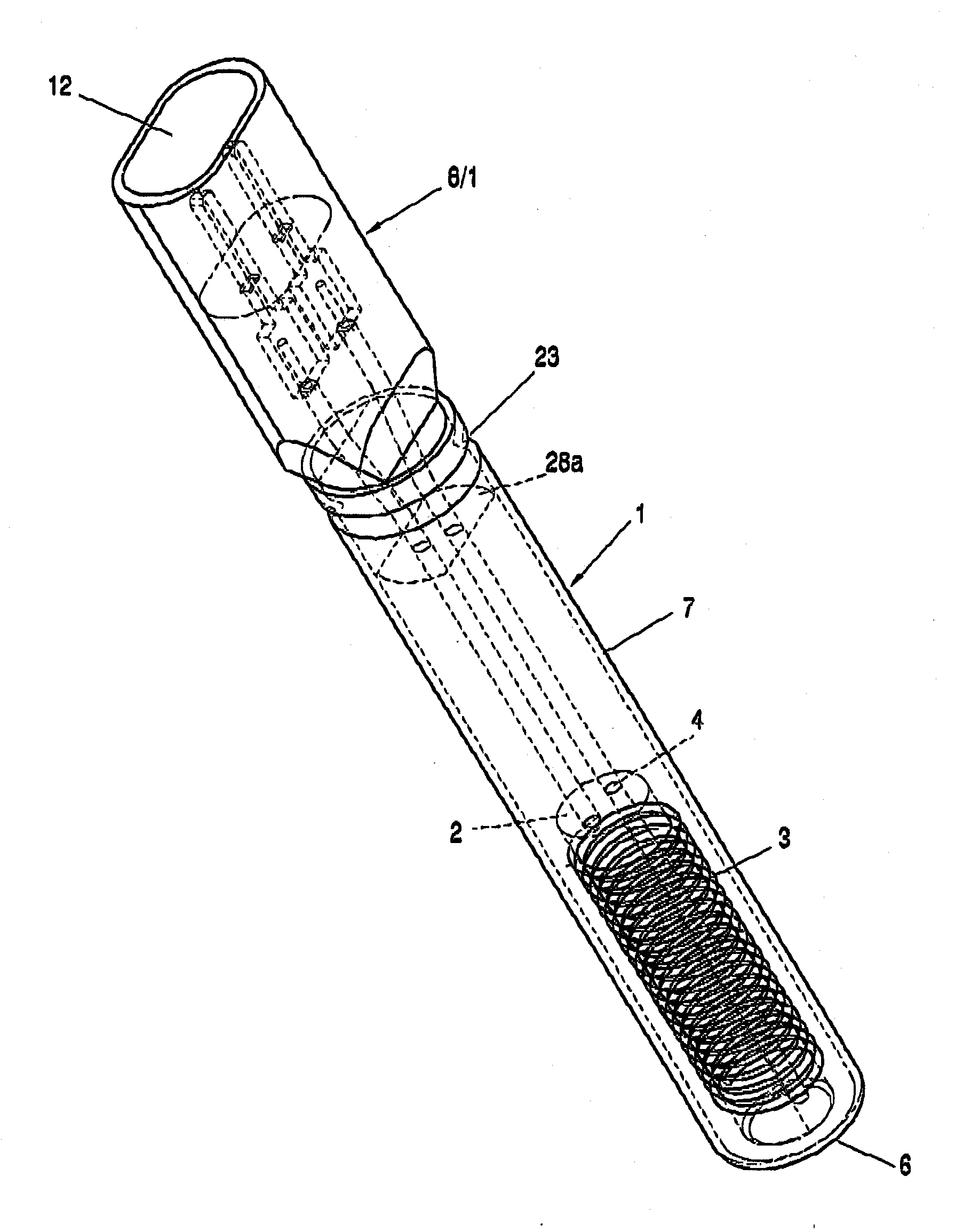
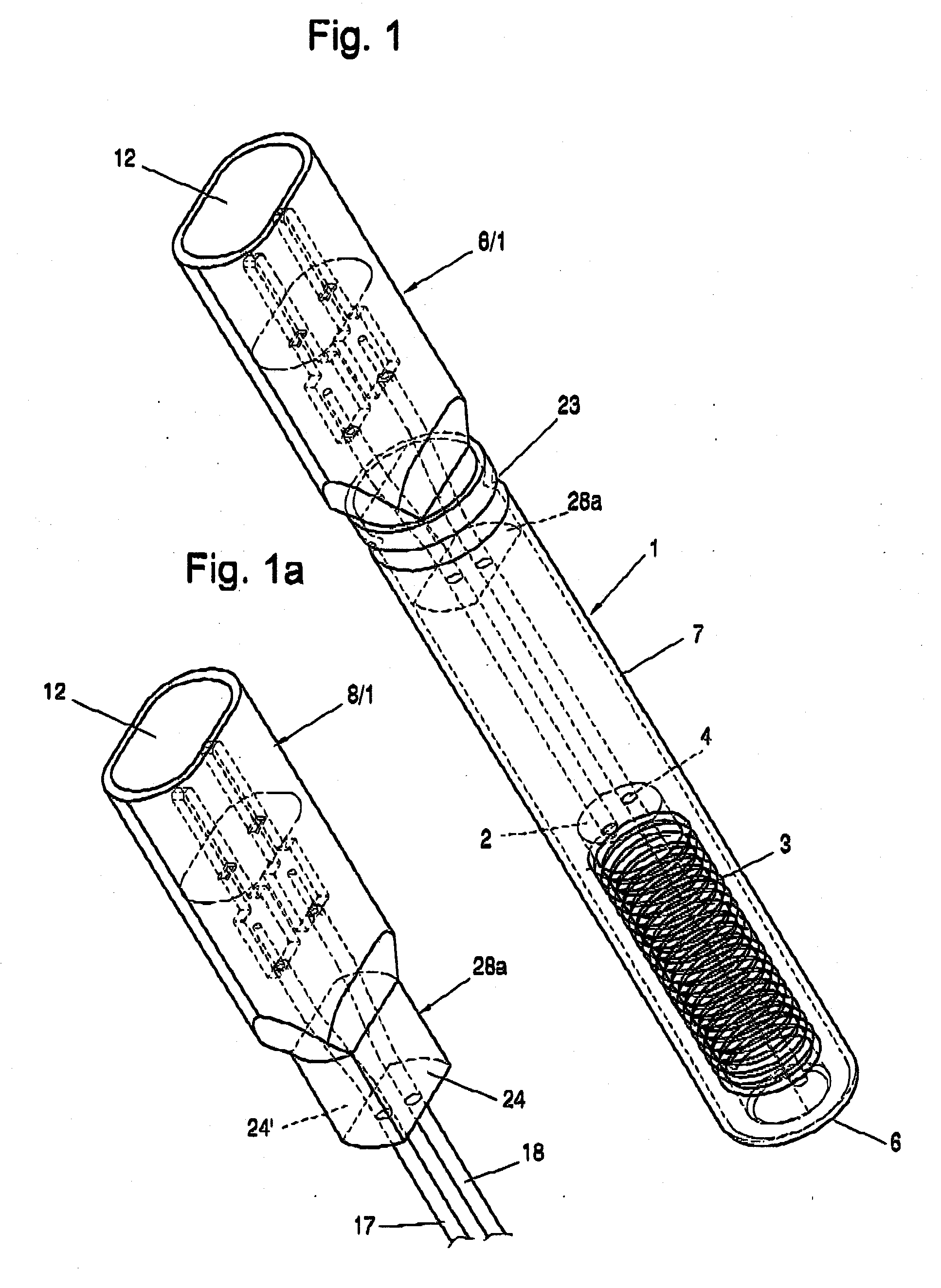
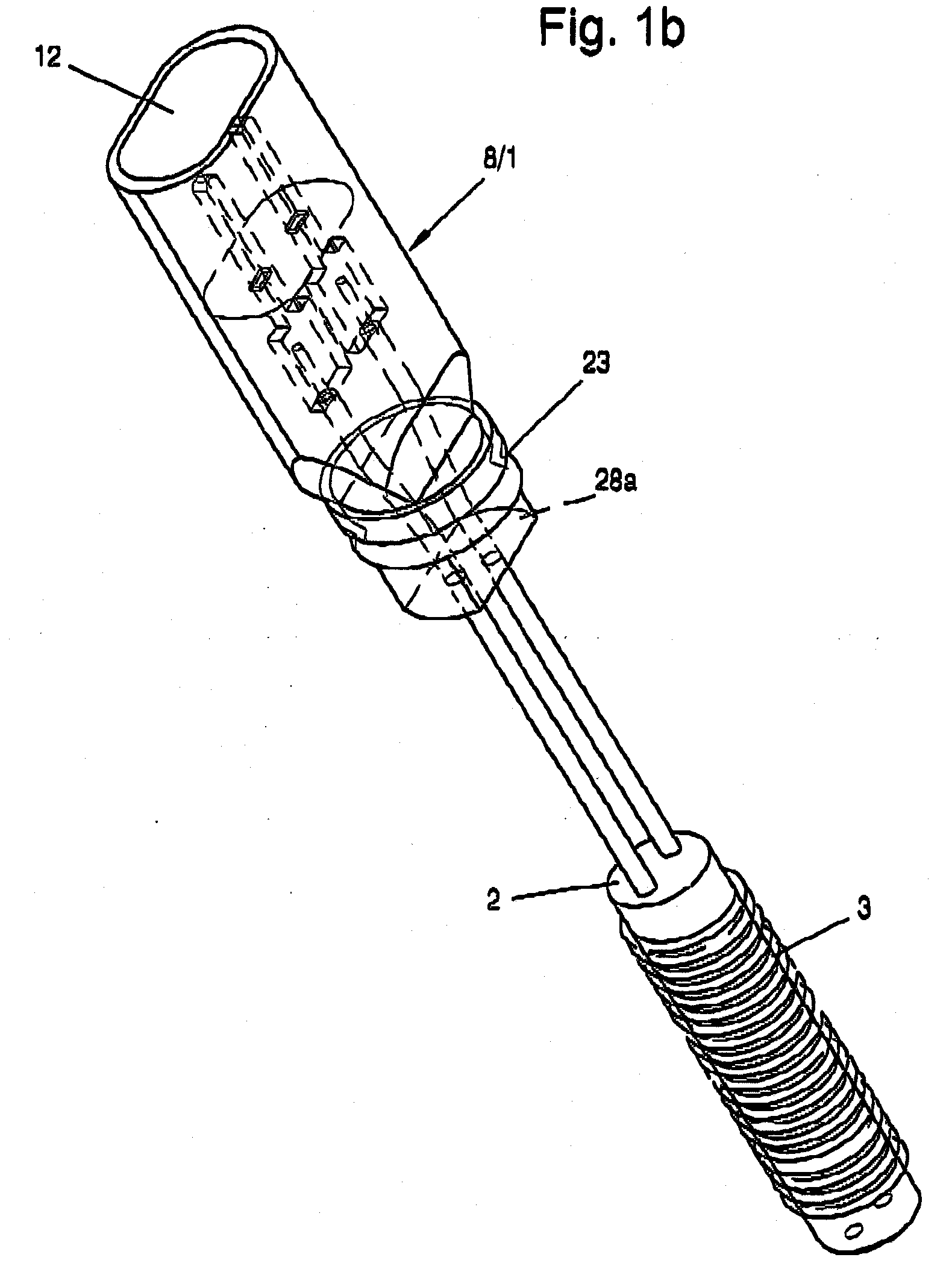
[0032]Referring to the drawings in particular, a heating cartridge 1 shown as an example in the drawings comprises a resistance wire winding 3 wound on a cylindrical winding support 2. The winding support 2 consists of an electrically non-conductive material, for example, ceramic, and it has at least one hole 4, which extends continuously axially and through which the lower end of the resistance wire winding 3 can be passed upwardly.

[0033]The winding support 2 with its resistance wire winding 3 wound upon it is embedded in an insulating material filling 5, which may consist, for example, of a metal oxide, preferably magnesium oxide, and which is located in a metal sheathing 7 closed at the lower front side 6.

[0034]A coupling element 8, which is manufactured from an injection-molded plastic and is designed as a connector plug 8 / 1 in the embodiment according to FIGS. 1, 1a, 1b as well as 4 through 11, is arranged at the upper end of the metal sheathing 7. This connector plug 8 / 1 is pr...


PUM


Abstract

A heating cartridge is intended especially for a thermostatic working valve. The cartridge is provided with a resistance wire winding (3), which is wound on a winding support (2) and is embedded in an insulating material filling (5) in a metal sheathing (7). The metal sheathing (7) is provided at one end (6) with a dimensionally stable coupling element (8) manufactured from a plastic, in which connecting lines (17, 18) are arranged, which electrically connect pluggable contact elements, especially pins (9, 10) of a connector plug, to the ends of the resistance wire winding (3). To simplify the manufacture and to obtain a compact design, the connecting lines (17, 18) are rigidly seated in the coupling element (8). The coupling element (8) is designed as a connector plug (8/1) and/or holder (8/2) and it has a connection section (28a, 28b, 28c), which protrudes into the open end of the metal sheathing (7) and which is fastened in the metal sheathing (7) in a non-positive and/or positive-locking manner by preferably radial pressing and forms a dimensionally stable structural unit with same.

Description

CROSS REFERENCE TO RELATED APPLICATIONS[0001]This application claims the benefit of priority under 35 U.S.C. § 119 of German Patent Application DE 20 2007 007 270.8 filed May 22, 2007 and German Patent Application DE 20 2007 008 404.8 filed Jun. 25, 2007, the entire contents of each of which are incorporated herein by reference.FIELD OF THE INVENTION[0002]The present invention pertains to a heating cartridge, especially a thermostatic working valve, with a resistance wire winding, which is wound on a winding support and is embedded in an insulating material filling in a metal sheathing, which is provided at one end with a dimensionally stable coupling element, which is manufactured from a plastic and in which connecting lines are arranged, which electrically connect pluggable contact elements, especially pins of a connector plug, to the ends of the resistance wire winding.BACKGROUND OF THE INVENTION[0003]In a heating cartridge of this type (DE 203 08 941 U1), the metal sheathing is ...

Claims


Application Information

Patent Timeline
IPC IPC(8): H05B3/06H05B3/48
CPCH05B3/06H05B3/48
Inventor SCHLIPF, ANDREAS
Owner TUERK & HILLINGER
Why Eureka
Try Eureka