Device for monitoring the level of a container

a technology for monitoring the fluid level of a container and a device, which is applied in the direction of fluid couplings, rotary clutches, instruments, etc., can solve the problems of device failure, magnet rupture, and float separation, and achieve simple and cost-efficient manufacturing of floats, and safe connection of both float parts

Inactive Publication Date: 2010-01-05
CONTINENTAL TEVES AG & CO OHG
View PDF9 Cites 6 Cited by
  • Summary
  • Abstract
  • Description
  • Claims
  • Application Information

AI Technical Summary

Benefits of technology

[0009]According to the invention, this object is achieved in that the float has a multipart design comprising a first float part and a second float part, and the magnet is encased and arranged between the two float parts. Thus, parts of a ruptured magnet are prevented from becoming detached from the float, and there is no risk that the float might be stuck.
[0012]Another favorable embodiment of the invention provides that the first float part has a stepped through-bore into which the second float part can be mounted by means of a press fit. The two float parts hence have a simple shape, which lends itself to ease of manufacture. Preferably, the magnet is arranged in an annular recess of the second float part, which is covered by a step of the first float part after the two float parts have been assembled.
[0013]In another favorable embodiment of the invention, the first float part can be slipped into the second float part, and the magnet is arranged in an annular recess on a top side of the second float part, which is covered by a bottom side of the first float part after the two float parts have been fitted. This renders simple joining of the two float parts possible without the use of tools.
[0015]In order to hold the two float parts together safely, means are provided at the first and second float parts, which ensure a safe connection of both float parts. To this end, the first float part at the bottom side favorably includes a projection, which snaps into a recess on the top side of the second float part after the two float parts have been joined. Thus, the float can be made as a prefabricated subassembly, without the risk of the single parts becoming detached during transport.
[0016]A simple and cost-efficient manufacturability of the float is achieved in that the two float parts are configured as a foamed plastic part.

Problems solved by technology

It is considered disadvantageous that the magnet can rupture and get detached from the float when it is damaged due to manufacture or during the assembly.
The float will be stuck thereby, causing failure of the device.

Method used


Image

  • Device for monitoring the level of a container
  • Device for monitoring the level of a container
  • Device for monitoring the level of a container

Examples


first embodiment

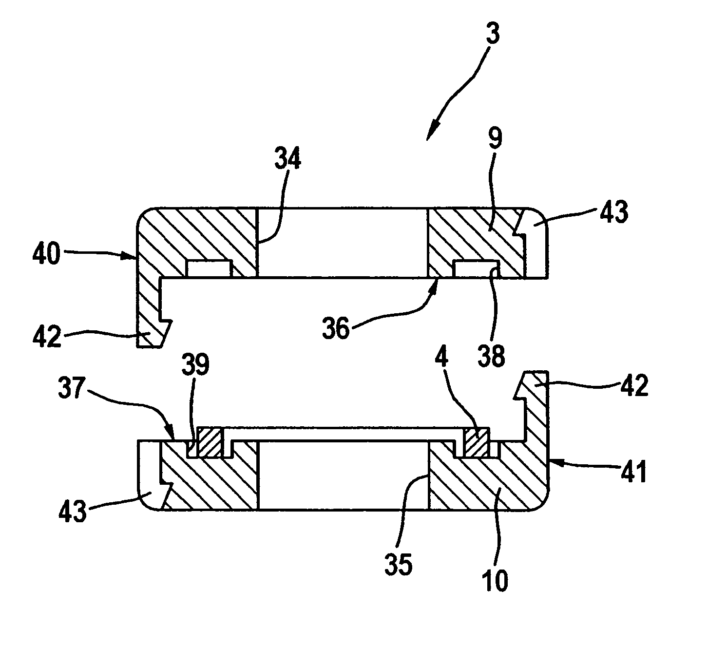
[0026]FIG. 2 shows a float 3 of a device of the invention for detecting the fluid level in a supply reservoir 1. As can be seen in FIG. 2, the float 3 has a first float part 9 and a second float part 10 with respectively one axial central bore 34, 35, and the two float parts 9, 10 are depicted prior to their joining. The central bores 34, 35 serve to guide the float 3 on the guide tube 2.

[0027]On an inside surface 36, 37, the two float parts 9, 10 include each one annular recess 38, 39, with the two recesses 38, 39 enclosing a common annular space after the two float parts 9, 10 have been joined. An annular magnet 4 is enclosed in this annular space, i.e. the magnet 4 is so-to-speak encapsulated in the float 3. This casing prevents parts of the magnet 4 from moving into the interior of the supply reservoir 1 in case the magnet 4 is ruptured due to defects of fabrication or during the assembly.

[0028]The two float parts 9, 10 include at an outside surface 40, 41 one or more locking el...

second embodiment

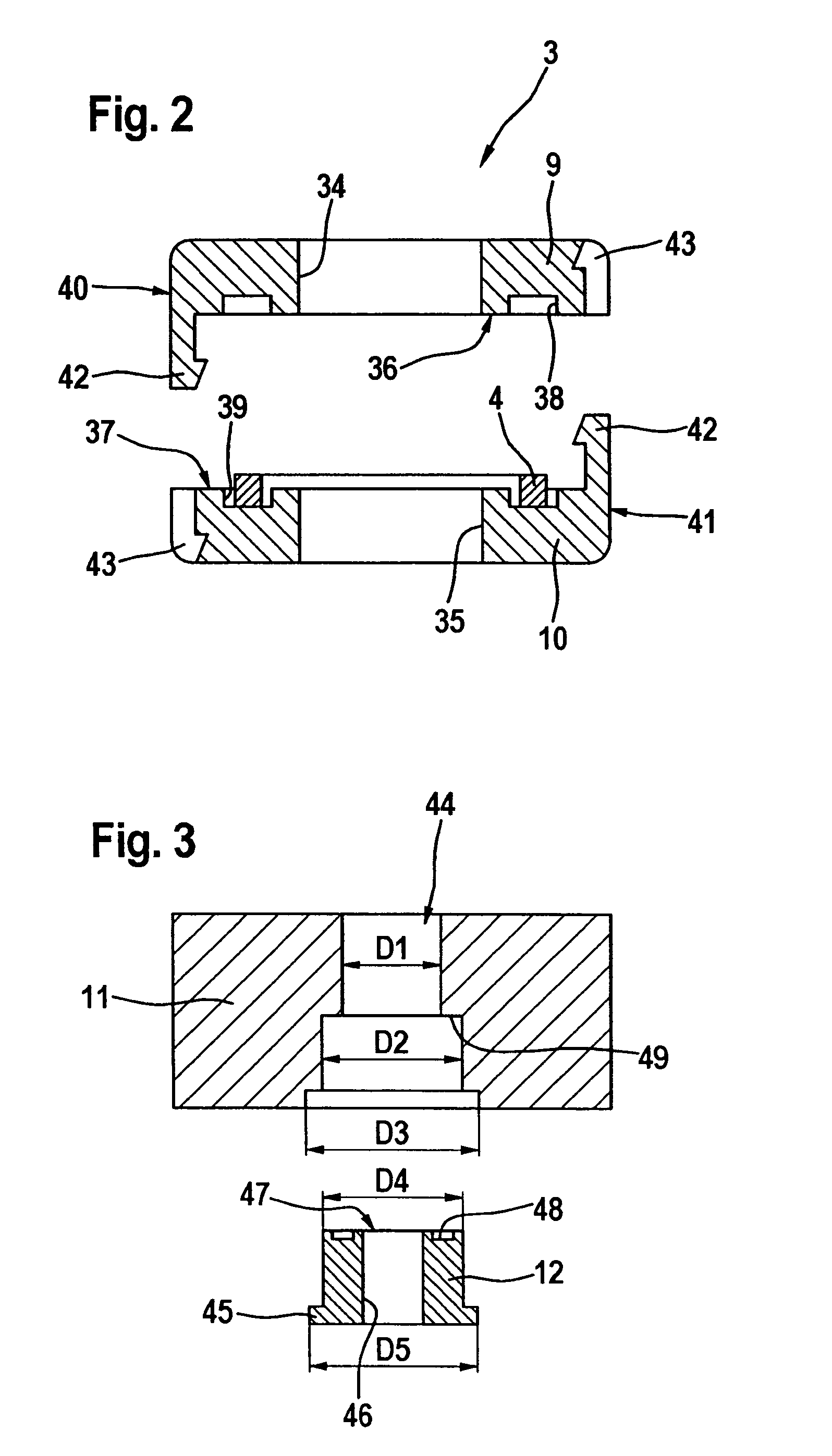
[0029]FIG. 3 shows a float 3 in a device of the invention for detecting the fluid level in a supply reservoir 1.

third embodiment

[0030]FIGS. 4 and 5 show a float 3 of a device of the invention for detecting the fluid level in a supply reservoir 1. The float of the present embodiment also includes a first and a second float part 51, 52, respectively, with the first float part 51 being adapted to be slipped into the second float part 52. For this purpose, the second float part 52 has a radial recess 53, into which the first float part 51 can be slipped in a guide manner. For guiding purposes, the sidewalls of the first float paart 51 include projections 55, while mating recesses 56 are provided at the sidewalls of the second float part 52.

[0031]Like the float of the first embodiment according to FIG. 2, the float 3 of the second embodiment is also of two-part design comprising a first float part 11 and a second float part 12.

[0032]The first float part 11 has a stepped axial central through-bore 44 with three different diameters D1, D2, D3, and D1 represents the smallest diameter, D2 the intermediate and D3 the ...


PUM


Abstract

A device for monitoring the level of a supply reservoir, in particular of a hydraulic motor vehicle brake system, comprising a float that has a magnet for actuating a switch or a sensor. The float has a multipart design comprising a first part and a second float part and the magnet is encased and arranged between the two float parts.

Description

[0001]This application is the U.S. national phase application of PCT International No. PCT / EP2005 / 051270, filed Mar. 18, 2005, which claims priority to German Patent Application No. DE 10 2004 015 486.4, filed Mar. 26, 2004 and German Patent Application No. DE 10 2004 061 357.5, filed Dec. 21, 2004.BACKGROUND OF THE INVENTION[0002]1. Technical Field[0003]The present invention relates to a device for monitoring the fluid level of a supply reservoir, in particular of a hydraulic motor vehicle brake system, comprising a float that has a magnet for actuating a switch or a sensor.[0004]2. Description of Related Art[0005]In a hydraulic motor vehicle brake system, the brake fluid required is contained in the supply reservoir, and the fluid level is monitored by the magnet that is used to activate the switching contacts. When the level of the brake fluid drops, the switching contacts are activated. This signal is evaluated in an electronic control unit, and the driver of the motor vehicle c...

Claims


Application Information

Patent Timeline
Patent Type & Authority Patents(United States)
IPC IPC(8): B60T17/22B60T11/26G01F23/74G01F23/76H01H36/02
CPCB60T17/225G01F23/74H01H36/02G01F23/76
Inventor TANDLER, PETERGUNTHER, STEFANJEBOUSEK, THOMASWALTER, JORG
Owner CONTINENTAL TEVES AG & CO OHG
Why Eureka
Try Eureka