
Dynamic blade distance ratio system and method

a distance ratio and blade technology, applied in mechanical machines/dredgers, transportation and packaging, gearing, etc., can solve the problems of increasing ground pressure on the front of the track, reducing ground pressure, and reducing the distance from the blade to the center of the front weight bearing member. , to achieve the effect of increasing the tractive effort of the machine, increasing the downforce and increasing the pull for

Inactive Publication Date: 2010-01-05
DEERE & CO
View PDF27 Cites 6 Cited by
  • Summary
  • Abstract
  • Description
  • Claims
  • Application Information

AI Technical Summary

Benefits of technology

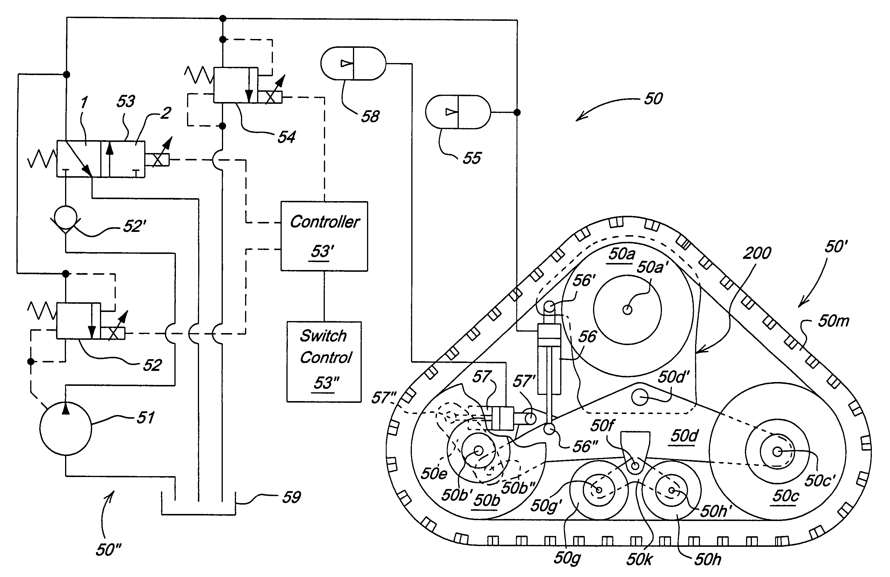
[0008]The invention improves the machine performance, i.e., the machine's ability to grade, by reducing the distance between the blade and the center of force under the front track system. This is accomplished by adding a hydraulic cylinder between the track frame and the track mounting frame which can increase the down-force on the front of the track frame. The cylinder is hydraulically connected to an accumulator and pressure regulating system so that the track can rotationally move around its mounting pivot and maintain contact with the ground.
[0010]An additional benefit of this system is that it enables the operator to artificially increase the downforce at the front of the track. In certain soil conditions, this can increase the tractive effort of the machine by forcing the track lug into the ground deeper than would be achieved without this feature enabled. The remainder of the track would then have a packed track to run in. This increased soil density under the track would enable the track to exert higher pull forces than would be otherwise achievable.

Problems solved by technology

The negative consequence of this arrangement is that the distance from the blade to the center of the front weight bearing member is greater than would be achieved with a conventional crawler.
This subsequently causes an increased ground pressure on the front of the track, and a reduced ground pressure at the rear of the track.

Method used


Image

  • Dynamic blade distance ratio system and method
  • Dynamic blade distance ratio system and method
  • Dynamic blade distance ratio system and method

Examples


Embodiment Construction

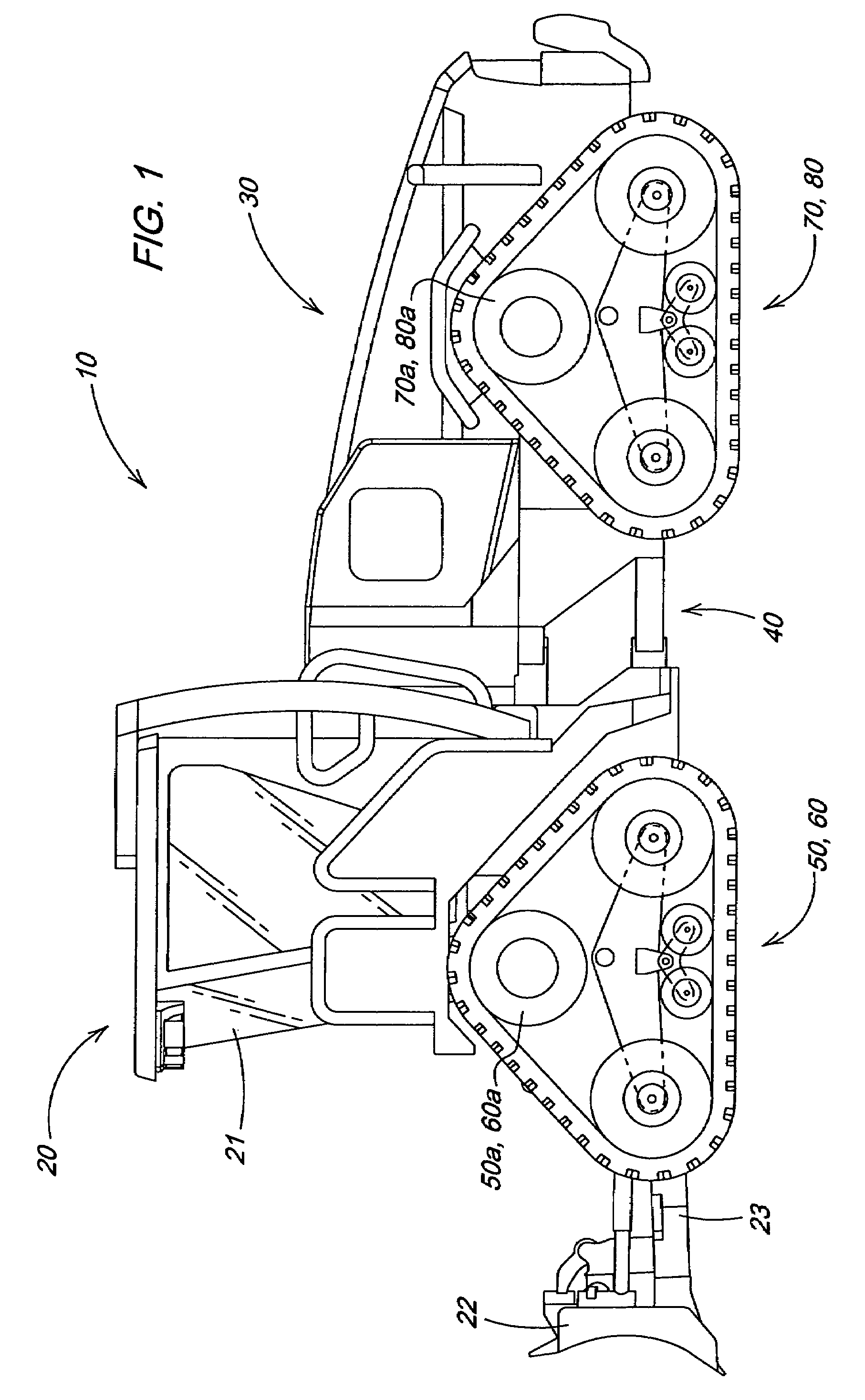
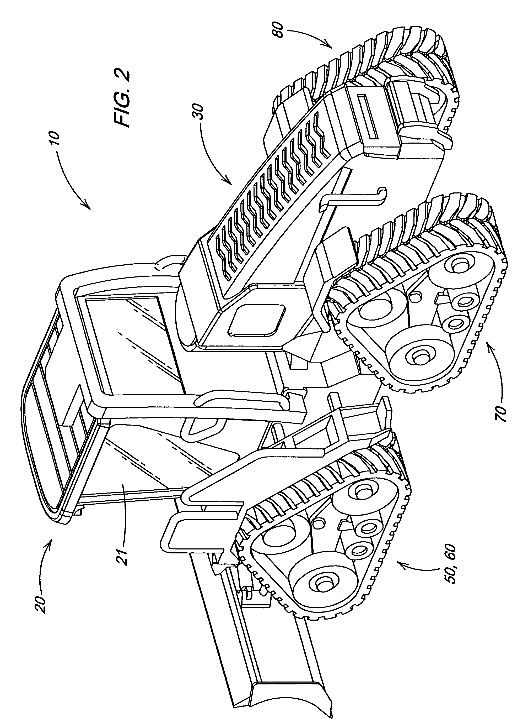
[0016]FIGS. 1 and 2 illustrate a vehicle in which the invention may be used. The particular vehicle illustrated in FIGS. 1 and 2 is a four track articulated dozer 10 having a front portion 20 a rear portion 30; an articulation mechanism 40 between the front portion 20 and the rear portion 30; first track systems 50, 60; and second track systems 70, 80. The front portion 20 includes a blade 22 and a blade mounting frame 23 as well as an operator cab 21.

[0017]FIG. 3 is a schematic of an exemplary embodiment of the invention. Included is an exemplary embodiment of the track system 50 which includes a track assembly 50′ and a hydraulic circuit 50″. The track assembly 50 is as illustrated in FIG. 3. A track frame 50d is pivotally mounted at track frame mounting pivot 50d′ to a mounting frame 200. A drive wheel 50a is also pivotally mounted to the mounting frame 200 at drive wheel pivot 50a′. A first main idler 50b is pivotally attached to tension link 50e at first main idler pivot 50b′ a...


PUM


Abstract

The blade ratio of an articulated work vehicle with multiple tracks is adjusted by shifting a load from the weight of the vehicle toward the front or rear of one or more of the tracks. The load may be shifted through the actuation of a hydraulic cylinder that applies a biasing load between a frame on which a track frame is mounted and a front or rear portion of the track frame.

Description

[0001]This document claims priority based on U.S. provisional; application Ser. No. 60 / 631,563, filed Nov. 29, 2004, and entitled DYNAMIC BLADE DISTANCE RATIO SYSTEM AND METHOD, under 35 U.S.C. 119(e).FIELD OF THE INVENTION[0002]The invention relates to blade distance ratio as a factor in the grading ability of dozers. More specifically, it relates to a system and method for dynamically adjusting the blade distance ratio on a four track articulated dozer.BACKGROUND OF THE INVENTION[0003]Current market trends indicate that crawler operators are using their machines for more finish grading work than has historically been done. Thus the need for dozers that can competently grade is growing. To support this trend, manufacturers continue to improve the machines ability to perform this work to the operators expectations.[0004]Key contributors of the dozers finish grading capability include such factors as machine balance, weight distribution, track length on ground, machine rigidity, and ...

Claims


Application Information

Patent Timeline
Patent Type & Authority Patents(United States)
IPC IPC(8): B62D55/116
CPCE02F9/02E02F9/0841
Inventor RADKE, DANIEL DEANNAGORCKA, JAMES ARTHURALLEN, LYAL DOUGLAS
Owner DEERE & CO
Learn More