Top plate conveyor device

a conveyor device and top plate technology, applied in the direction of conveyor parts, transportation and packaging, rollers, etc., can solve the problems of difficult sliding of accumulated articles on the loading surface, large driving force of the conveyor device, etc., to achieve the effect of reducing vibration and noise, preventing generation of elongation, and simple structure of the top plate conveyor devi

Inactive Publication Date: 2010-01-05
TSUBAKIMOTO CHAIN CO
View PDF7 Cites 7 Cited by
  • Summary
  • Abstract
  • Description
  • Claims
  • Application Information

AI Technical Summary

Benefits of technology

[0016]When the top plate conveyor device of the present invention has a toothed belt made of rubber and top plates each removably secured to the toothed belt by engagement members and the back surfaces of the article loading top plates are supported by guide rails, vibrations and noises can be reduced and the generation of elongation can be also prevented. Additionally the following peculiar effects can be obtained.
[0017]In the top plate conveyor device of each embodiment of the present invention, said engagement members include sandwiching portions provided on back surfaces of said top plates, which sandwich the said toothed belt from both outer sides in the width direction and pawl portions, which snap-connect to said toothed belt by pawls on the front side of the sandwiching portions so that said engagement members embrace said toothed belt to engage with it, the structure of the top plate conveyor device is simple and the top plates and the toothed belt can be reliably secured to each other to form a substantially continuous loading surface. Thus the production assembly and handling of the top plate conveyor device become easy and the structure thereof in which strength is not decreased and damage is not liable to occur can be obtained.
[0018]In the top plate conveyor device of one embodiment of the invention, said engagement members are formed such that each of said engagement members engages with a valley portion of said toothed belt, the engagement members can be shortened and the top plates can be miniaturized. Thus the production assembly and handling of the top plate conveyor device further become easy.
[0019]In the top plate conveyor device of a second embodiment of the invention, said engagement members are formed such that each of said engagement members engages with a crest portion of said toothed belt, a distance of the engagement portion to a front end pawl portion can be made longer. Thus even if rigidity of the top plate is enhanced, the elasticity for snap connection between sandwiching portions of the engagement portions can be acquired so that the production assembly and handling of the top plate conveyor device become easy.
[0020]When in each embodiment of the top plate conveyor device, said top plates have overhanging side edge portions which extend beyond the outer sides of the toothed belt, and the back surfaces of the overhanging portions of the article loading top plates are supported by guide rails on both right and left outer sides of said engagement members in the width direction. The guide rails slidably support the undersurfaces of the overhanging portions of the top plates, which are of a rigid material which has a small friction coefficient. Thus vibrations and noises are reduced and at the same time necessary driving force can be decreased.

Problems solved by technology

Such a conveyor device 700, where rubber such as urethane or the like used in the toothed belt 720 which has a higher frictional coefficient as compared with resin used in the top plates of a usual top plate conveyor device, there were problems that the conveyor device needs large driving force for driving a conveyor due to frictional resistance with a guide rail 740 on a back surface and sliding of accumulated articles on the loading surface is difficult.

Method used


Image

  • Top plate conveyor device
  • Top plate conveyor device
  • Top plate conveyor device

Examples


first embodiment

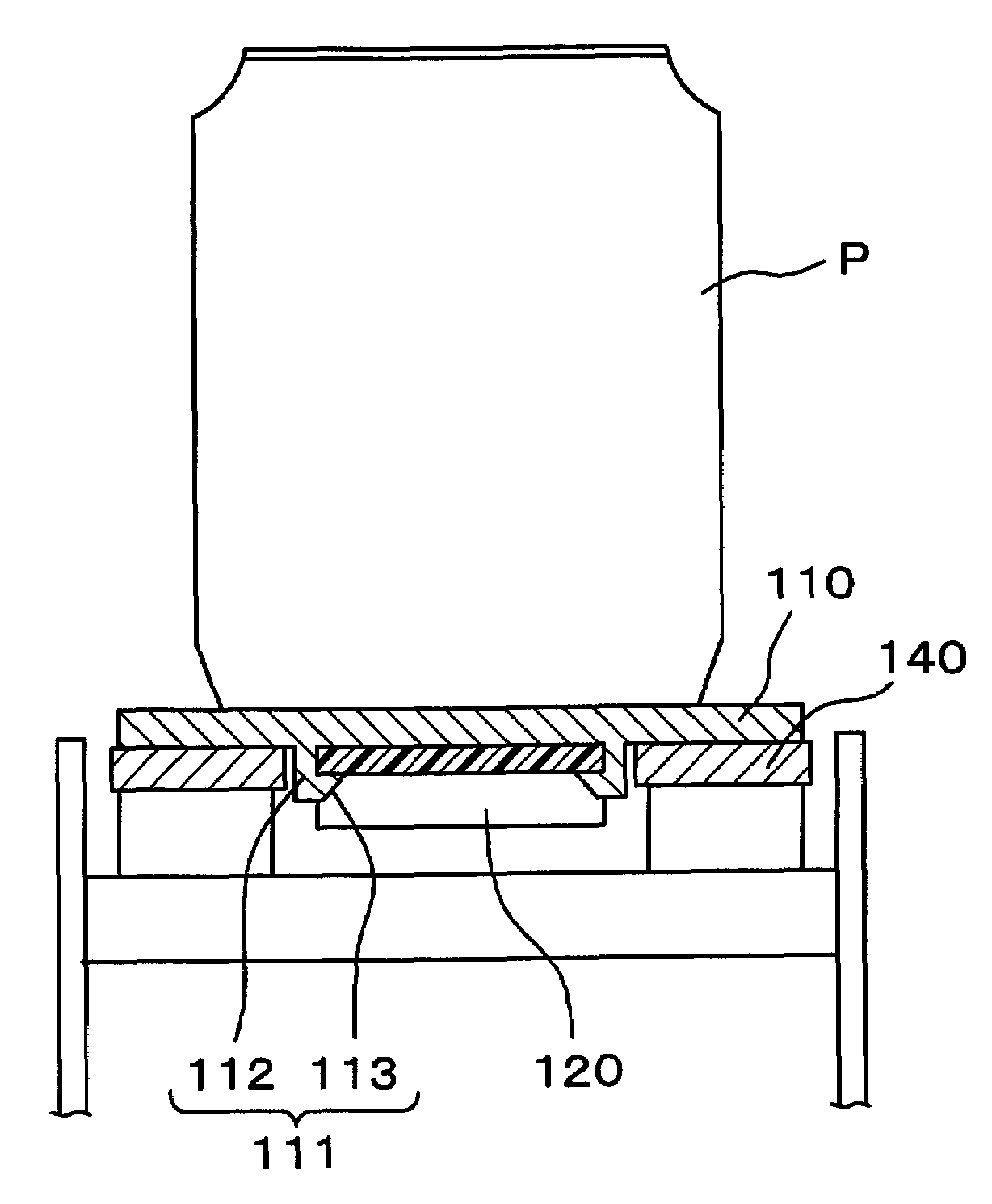
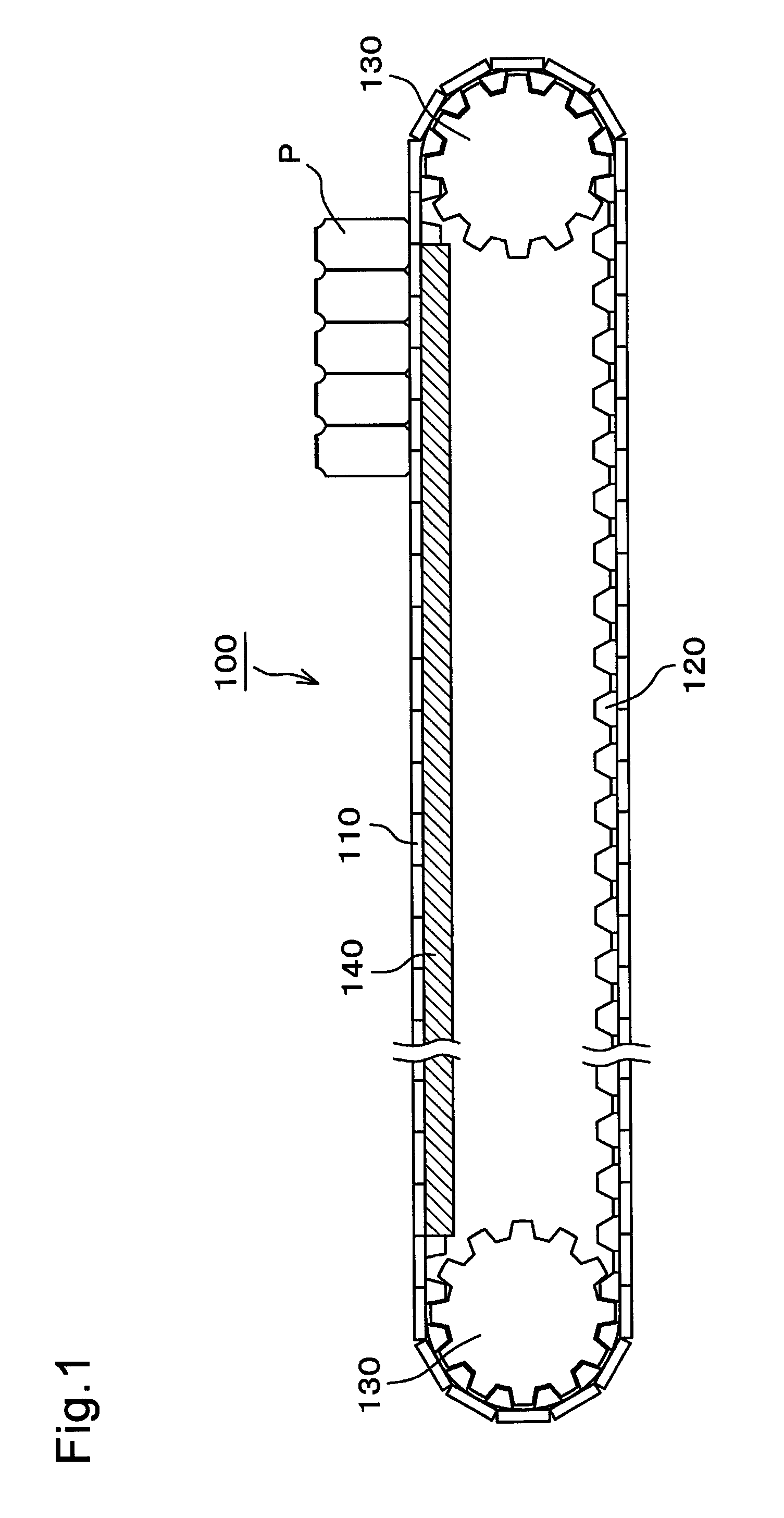
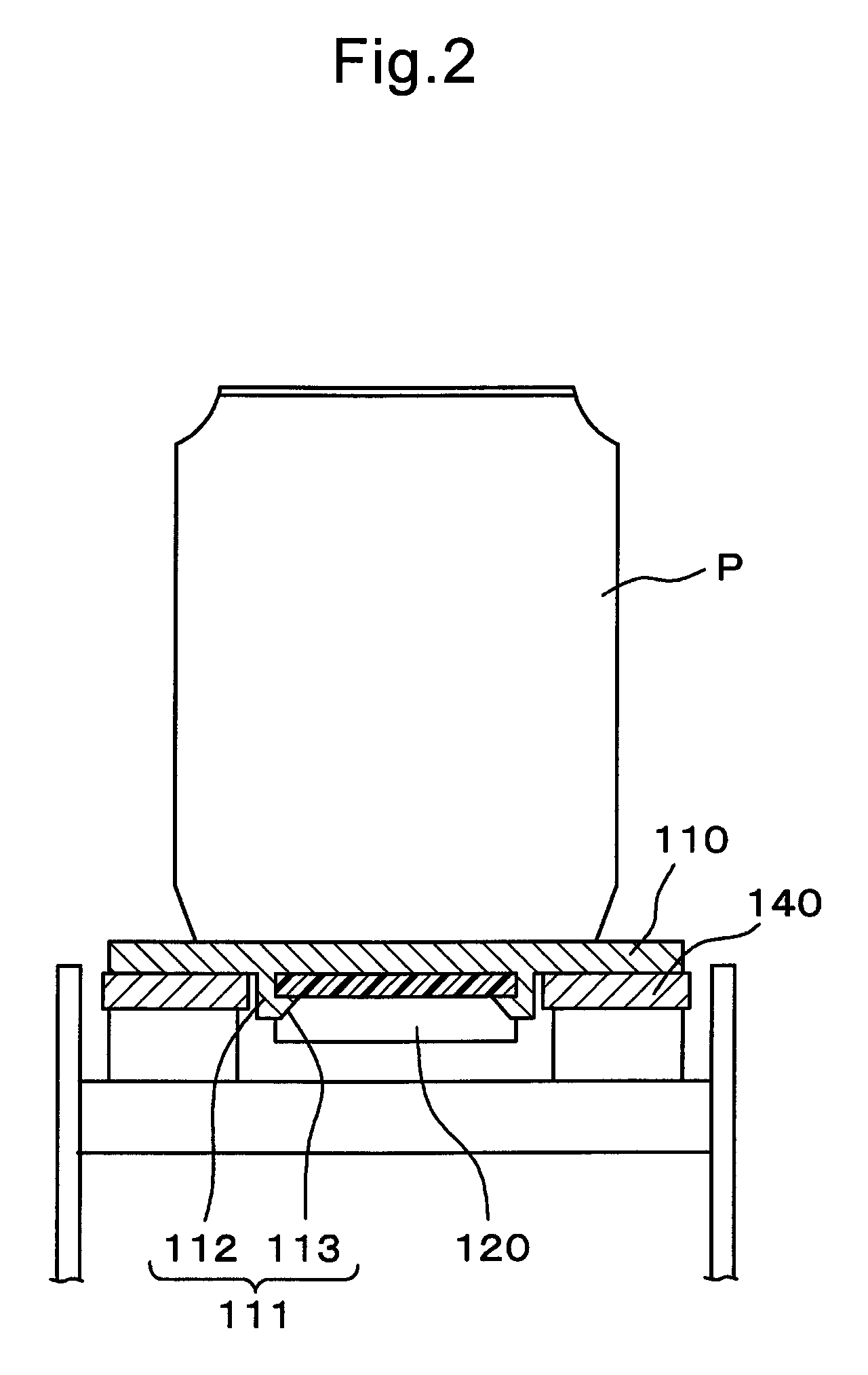
[0033]Referring to FIGS. 1-3, a top plate conveyor device 100, which is the present invention, is formed such that a number of top plates 110 are engaged with a toothed belt 120 to provide an endless a chain-shaped member which circularly travels between two sprockets 130, as shown in FIG. 1.

[0034]The upper surface of the top plate conveyor device 100 is used as a loading surface for conveying articles P. Guide rails 140 come into sliding contact with overhanging side portions of the traveling top plates 110 to support them thereby ensuring flatness of the loading surface. The guide rails 140 are provided on both right and left outer sides in a width direction of the top plate conveyor device 100 as shown in FIG. 2. There is a small space between the adjacent side of the of the belt 120 and each guide rail 140. The guide rails 140 come into sliding contact with back surfaces of the overhanging side portions of the top plates 110. Between the side portions, outside of right and left ...

second embodiment

[0042]the present invention is illustrated in FIGS. 4 and 5. In this embodiment, a top plate 210 of a top plate conveyor device 200, is engaged with a crest portion 222 of a toothed belt 220.

[0043]The top plate 210 of the top plate conveyor device 200 in this second embodiment of the present invention, is vertically provided with engagement members 211, which engage with the toothed belt 220 on a back surface of a loading surface where articles P are loaded.

[0044]The engagement member 211 includes a sandwiching portion 212, which sandwiches the toothed belt 220 from both its outer sides in the width direction together with the other sandwiching portion 212, and includes a pawl portion 213, which is snap-fitted to the toothed belt 220 on the confronting side of the sandwiching portion 212. As shown in FIG. 5, the back surface of the toothed belt 220 includes a tooth portion 221 composed of a crest portion 222 and a valley portion 223.

[0045]The length of the sandwiching portion 212 is...


PUM


Abstract

A top plate conveyor device, in which vibrations and noises are reduced, and the structure is simple and the production assembly and handling are easy. Top plates 110 are removably provided on a rubber toothed belt 120 by engagement members 111 provided on the back surfaces of the top plates 110, and engagement members 111 include sandwiching portions 112 which sandwich the toothed belt 120 from both outer sides in the width direction and terminate in pawl portions 113, which snap-connect the top plates to the toothed belt 120.

Description

FIELD OF INVENTION[0001]The present invention relates to an article transferring top plate conveyor device for transferring articles loaded on top plates.BACKGROUND OF THE INVENTION[0002]As top plate conveyor devices, a top plate conveyor device has been known in which adjacent top plates are rotatably connected to each other by connecting pins or the like to form a chain shaped-element as a configuration for endlessly connecting a plurality of top plates to each other.[0003]One such device is shown in FIG. 6. A top plate conveyor device 600, has a number of top plates 610 rotatably connected to each other by connecting pins 615 to form an endless chain shape and are formed such that the top plate conveyor device is stretched between sprockets 630 to load articles thereon and convey them. Guide rails 640 are provided along the top run, i.e. the conveying portion, of the conveyor to underlie the back surfaces of the chain-shaped top plates 610 to support the article loading surface.[...

Claims


Application Information

Patent Timeline
Patent Type & Authority Patents(United States)
IPC IPC(8): B65G29/00
CPCB65G17/44B65G17/065
Inventor ISHIKAWA, MASAYUKIUENO, YASUNORI
Owner TSUBAKIMOTO CHAIN CO
Why Eureka
Try Eureka