Vehicle display apparatus

a technology for display devices and vehicles, applied in navigation instruments, identification means, instruments, etc., can solve problems such as inattention of drivers to display content, and achieve the effect of increasing driver's attention and promoting driver's concern for display conten

Inactive Publication Date: 2010-01-05
DENSO CORP
View PDF14 Cites 61 Cited by
  • Summary
  • Abstract
  • Description
  • Claims
  • Application Information

AI Technical Summary

Benefits of technology

[0015]The present invention has been made in consideration of the foregoing. It is therefore an object of the present invention to provide a vehicle display apparatus capable of increasing driver's attention to a more important meter image or the like and promoting driver's concern for a display content by means of a visual effect when the inside of an instrument panel is used to display both a relatively more prioritized image such as the meter image and a relatively less prioritized image such as a navigation image.

Problems solved by technology

Simultaneously displaying the meter image or the like and the navigation image provides an unattractive visual effect and tends to make a driver inattentive to a display content.

Method used


Image

  • Vehicle display apparatus
  • Vehicle display apparatus
  • Vehicle display apparatus

Examples


first embodiment

1. First Embodiment

[0030](Construction Description)

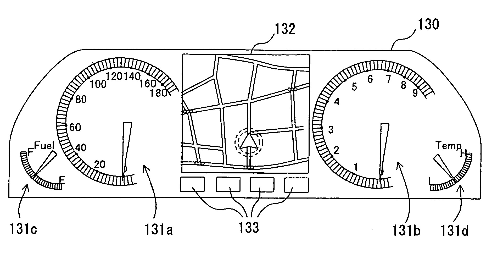
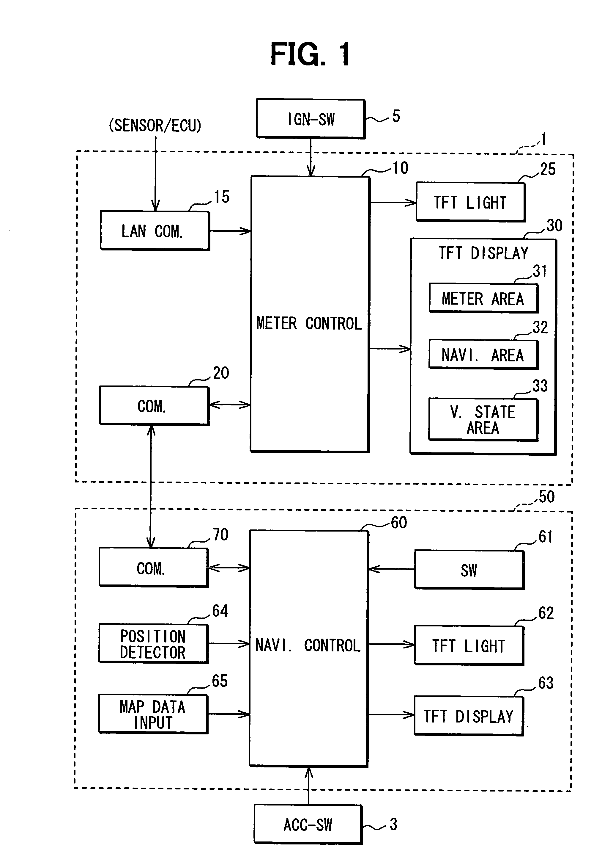
[0031]FIG. 1 is a block diagram showing an overview construction of a vehicle display apparatus 1 according to a first embodiment and a navigation apparatus 50 connected thereto. FIG. 2 is a front view of the vehicle display apparatus 1. The vehicle display apparatus 1 and the navigation apparatus 50 include the following components and are mounted on a vehicle for use. The vehicle display apparatus 1 will be first described.

[0032]1>

[0033]The vehicle display apparatus 1 includes a meter control unit 10, an interior LAN (Local Area Network) communication unit 15, a communication unit 20, a TFT (Thin Film Transistor) light source 25, and a TFT (Thin Film Transistor) display device 30.

[0034]The interior LAN communication unit 15 provides communication between various ECUs (Electronic Control Units) and alarm sensors connected to an interior LAN (not shown). The ECUs include an engine ECU and an AT (Automatic Transmission)-ECU, for exam...

second embodiment

2. Second Embodiment

[0078](Construction Description)

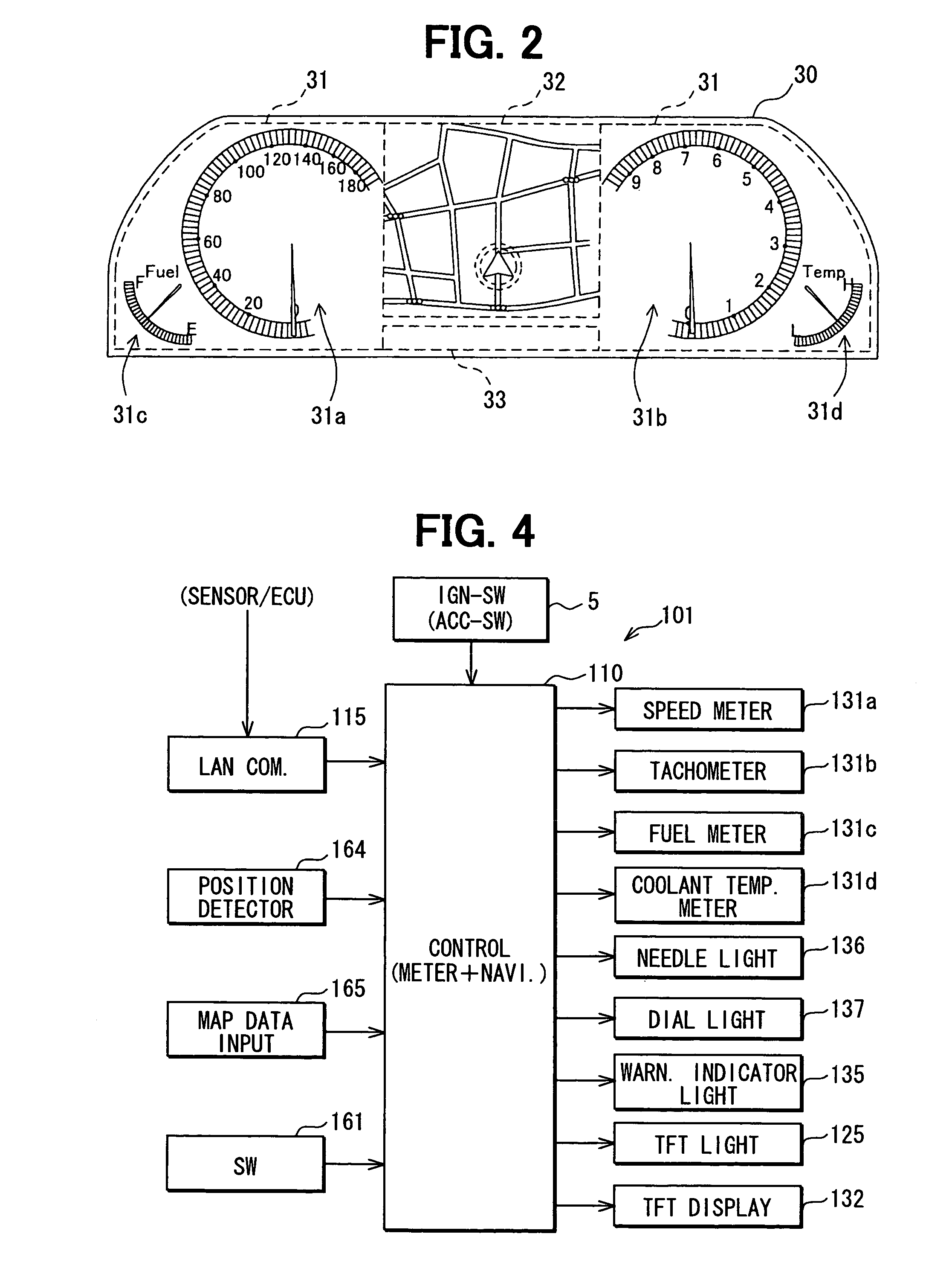
[0079]FIG. 4 is a block diagram showing an overview construction of a vehicle display apparatus 101. FIG. 5 is a front view of the vehicle display apparatus 101. The above-mentioned vehicle display apparatus 1 according to the first embodiment assumes a so-called digital meter that also displays the meter as an image. By contrast, the vehicle display apparatus 101 according to the second embodiment assumes a mechanical meter.

[0080]The vehicle display apparatus 101 includes a meter control unit 110, an interior LAN communication unit 115, a speed meter 131a, a tachometer 131b, a fuel meter 131c, a coolant temperature meter 131d, a needle light source 136, a dial light source 137, warning indicators 133 (see FIG. 5), a warning indicator light source 135, a TFT light source 125, a TFT display device 132, an operation switch group 161, a position detector 164, and a map data input device 165. The position detector 164 detects the vehic...

third embodiment

3. Third Embodiment

[0112](Construction Description)

[0113]The system construction itself is similar to the vehicle display apparatus 1 and the navigation apparatus 50 connected thereto according to the first embodiment shown in FIG. 1. Accordingly, the same components are not described. Differences are additional signals applied to the meter control unit 10 via the interior LAN communication unit 15. These signals include image signals representing the rear and sides of the vehicle and a signal from a sensor to detect whether or not to wear a seat belt.

[0114]Specifically, FIG. 7 shows rear view (α). A CCD (Charge-Coupled Device) camera is provided to capture an image at the rear of the vehicle. FIG. 7 also shows side rear view (β) and side front view (γ). CCD cameras are provided to capture an image at the side of the vehicle.

[0115]To capture an image at the side of the vehicle, the CCD cameras are provided for a side mirror 40 opposite the driver's seat as shown in FIG. 7. The side ...


PUM


Abstract

When an ignition switch is turned on to display an image on a display apparatus, the display apparatus first displays a needle image of meter images and a warning indicator image. Out of the meter images, the display apparatus displays the needle image for a specified time period (e.g., 0.2 seconds), and then displays a dial image. After displaying the dial image for a specified time period, the display apparatus displays a navigation image. The specified time period may be set to 0.5 through 1.0 second, for example, long enough to visually check or recognize display of the meter image and the warning indicator image. Accordingly, it is possible to visually check the meter image and the warning indicator image while the navigation image is not displayed.

Description

CROSS REFERENCE TO RELATED APPLICATION[0001]This application is based on and incorporates herein by reference Japanese Patent Applications No. 2005-298912 filed on Oct. 13, 2005 and No. 2006-39436 filed on Feb. 16, 2006. This application is also related to U.S. application Ser. No. 11 / 543,090, entitled “VEHICLE DISPLAY APPARATUS,” filed on Oct. 5, 2006.FIELD OF THE INVENTION[0002]The present invention relates to a vehicle display apparatus that is placed near a driver and displays visual information about a meter and navigation.BACKGROUND OF THE INVENTION[0003]A navigation apparatus outputs visual information such as map, route, and facility information. Generally, the visual information is displayed on a display apparatus such as a liquid crystal display provided for a vehicle's center console. In this manner, the visual information is transmitted to the driver. Such display apparatus provided for the center console necessitates the driver to frequently move his or her line of sigh...

Claims


Application Information

Patent Timeline
Patent Type & Authority Patents(United States)
IPC IPC(8): B60Q1/00
CPCG01C21/265G01C21/367
Inventor KATO, MIKIUCHIDA, TSUNEOTAGUCHI, KIYOTAKAWATANABE, YOSHINORIKAWAKAMI, HIDEHIKO
Owner DENSO CORP
Why Eureka
Try Eureka