
Method and apparatus for three dimensional tomographic image reconstruction of objects

a three-dimensional tomographic image and reconstruction technology, applied in the field of data processing systems, can solve the problems of weather conditions and air quality, and the accuracy of registration becomes extremely difficult, and the limited range of laser imaging detection and range systems

Inactive Publication Date: 2010-01-05
THE BOEING CO
View PDF8 Cites 22 Cited by
  • Summary
  • Abstract
  • Description
  • Claims
  • Application Information

AI Technical Summary

Benefits of technology

This approach enables accurate three-dimensional image reconstruction of objects in cluttered environments and adverse weather conditions, improving data collection efficiency and reducing dependency on weather conditions, while maintaining adaptability and self-healing capabilities.

Problems solved by technology

In the presence of clutter and when the object is moving, an accurate registration becomes extremely challenging.
One shortcoming of this type of system is that laser imaging detection and ranging systems are limited by weather conditions and air quality.

Method used


Image

  • Method and apparatus for three dimensional tomographic image reconstruction of objects
  • Method and apparatus for three dimensional tomographic image reconstruction of objects
  • Method and apparatus for three dimensional tomographic image reconstruction of objects

Examples


Embodiment Construction

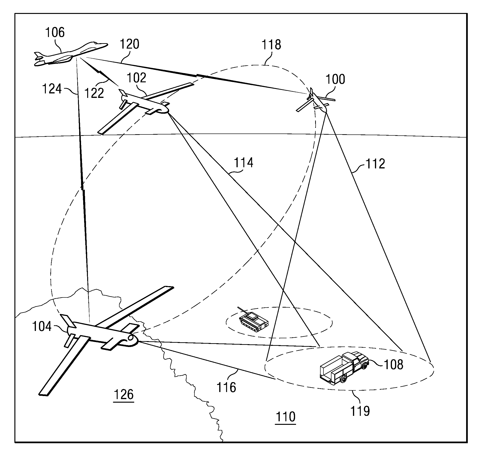
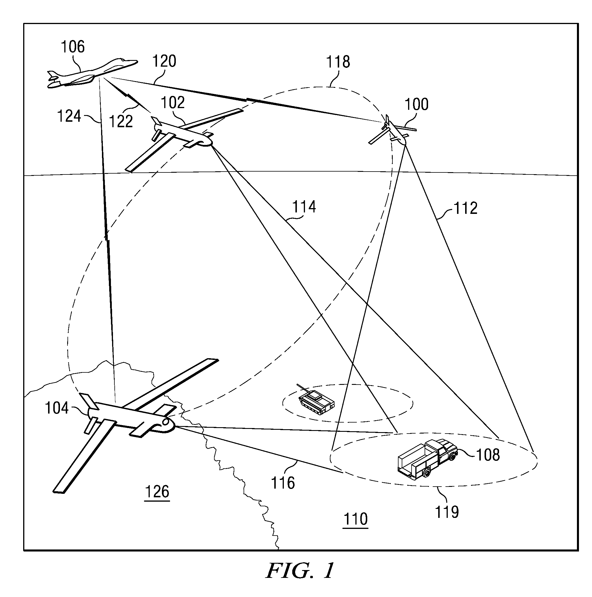
[0038]With reference now to the figures and in particular with reference to FIG. 1, a system for creating a three dimensional image of a target object is depicted in accordance with an advantageous embodiment. In this example, the system includes a coordinated network centric data collection system and a central node. The coordinated network centric data collection system contains nodes in the form of unmanned aerial vehicle (UAV) 100, unmanned aerial vehicle 102, and unmanned aerial vehicle 104. The central node takes the form of aircraft 106 in this particular example.

[0039]Unmanned aerial vehicles 100, 102, and 104 collect data for target object 108 on ground 110. In these particular examples, the data is radar data. Radar data is generated by unmanned aerial vehicles 100, 102, and 104 projecting beams or cones of electromagnetic radiation from radar systems onto target object 108 and collecting the data that returns from those beams or cones. In this example, unmanned aerial veh...


PUM


Abstract

In accordance with an embodiment, a system includes a plurality of vehicles and a central node. The plurality of vehicles each have radar systems used to collect radar data about the target object. Each in the plurality of vehicles moves in a path to collect a portion of the radar data using a sampling map to coordinate collection of the radar data by the plurality of vehicles and communicates with every other vehicle to identify uncollected portions of the radar data. The central node is in communication with the plurality of vehicles, wherein the central node receives the radar data from the plurality of vehicles and creates a three dimensional image from the radar data received from the plurality of vehicles using a tomographic reconstruction process.

Description

BACKGROUND INFORMATION[0001]1. Field[0002]The present invention relates generally to an improved data processing system and in particular to a method and apparatus for processing image data. Still more particularly, the present invention relates to a computer implemented method, apparatus, and computer usable program code for three dimensional tomographic image reconstruction of objects.[0003]2. Background[0004]Identifying targets or objects by their features of interest in a three dimensional space is a desirable objective for use in identifying unknown objects. Currently, synthetic aperture radar (SAR) is a form of coherent radar in which sophisticated post-processing of data obtained by this type of system is used to produce three dimensional radar images. Stereo synthetic aperture radar systems extract range information from the geometric disparity between two different views on the same point for a three dimensional object. With this type of system, a registration technique is ...

Claims


Application Information

Patent Timeline
Patent Type & Authority Patents(United States)
IPC IPC(8): G01S13/89
CPCG01S7/003G01S13/87G01S13/89
Inventor CHENG, SHIRLEY N.WITTENBERG, PETER
Owner THE BOEING CO
Learn More