Telescope based calibration of a three dimensional optical scanner

Active Publication Date: 2010-01-05
LEICA GEOSYSTEMS AG
View PDF3 Cites 15 Cited by
  • Summary
  • Abstract
  • Description
  • Claims
  • Application Information

AI Technical Summary

Benefits of technology

[0018]These and other objects and features of the present invention will become more fully apparent from the follo

Problems solved by technology

Such an approach suffers from at least three problems.
Second, if the targets move between the time the targets are measured with the secondary measuring system and when the targets are measured by the scanner being calibrated, perhaps because the targets are, for example, affixed to portions of a building which deform with sunlight or other factors over time, these motions will introduce systematic errors into the calibration parameters.
Third, the ability to estimate the calibration parameters is no better than the ability to locate the targets with the scanner and the secondary measuring system.
This requires a large stable space.
The size of the space is costly and tends to aggravate the second problem; that is, targets remaining stable or fixed in position over time.
However, if mirrors move

Method used


Image

  • Telescope based calibration of a three dimensional optical scanner
  • Telescope based calibration of a three dimensional optical scanner
  • Telescope based calibration of a three dimensional optical scanner

Examples


Embodiment Construction

[0032]Calibration of total stations, and other scanning systems, is a well known process. However, this process is not well suited to three dimensional optical scanning systems including LIDAR scanners. Three dimensional optical scanning systems have additional degrees of uncertainty in their calibrations compared to total stations. These additional degrees of uncertainty result from, among other things, mirrors being using to change the position of the laser beam used in the scan. To overcome these problems, an alternative calibration methodology is needed and disclosed hereinafter.

I. Antipodal Calibration Rig

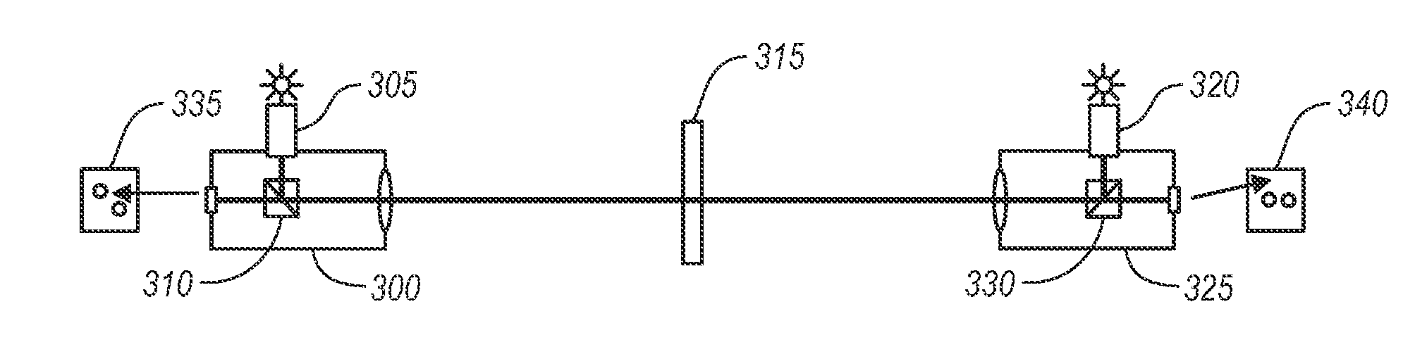
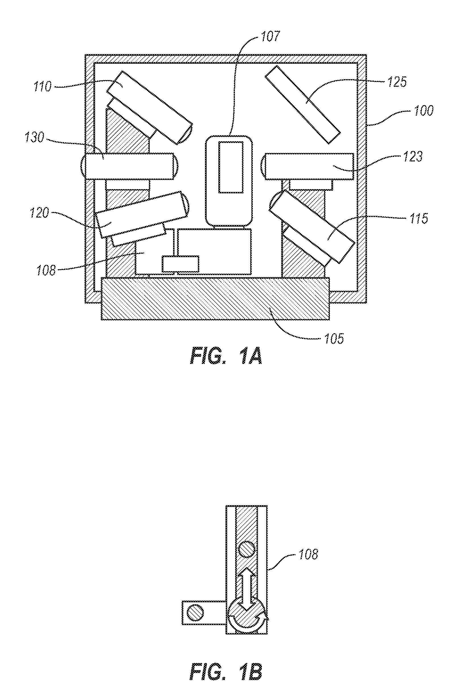
[0033]FIG. 1A illustrates an example of an antipodal calibration rig 100. This example contains an antipodal telescope pair, 110 and 115, as well as other telescopes. The antipodal calibration rig 100 can be used for angular calibrations (as described in section III below), tilt calibrations (as described in section IV below), and / or range calibrations (as described in section...


PUM


Abstract

An embodiment of the invention includes using a set of telescopes to calibrate a three dimensional optical scanner. Three separate calibrations are disclosed for a survey grade calibration: (1) angular calibration, implemented using at least one anti-podal pair of telescopes, (2) range calibration, implemented using at least one telescope mounted fiber recirculator, and (3) tilt calibration, implemented using at least one pair of telescopes not mounted in anti-podal configuration and an integral tilt table. Methods for aligning or measuring the mis-alignment between anti-podal telescope pairs are also described.

Description

CROSS-REFERENCE TO RELATED APPLICATIONS[0001]Not applicable.BACKGROUND OF THE INVENTION[0002]The acquisition of data and subsequent generation of computer models for real-world objects is of interest in many industries and for many applications including architecture, physical plant design, entertainment applications (e.g., in movies and games), surveying, manufacturing quality control, medical imaging and construction, as well as cartography and geography applications. In order to obtain accurate 3D models of an object, as well as the area in which that object exists in the real world, it is necessary to take accurate measurements, or samplings of surfaces that make up the object, and elements of the surrounding area. Historically, this sampling was carried out using techniques that provided samples at the rate of tens or hundreds per hour at most.[0003]Recent advances in scanning technology, such as technologies utilizing LIDAR scanning, have resulted in the ability to collect bil...

Claims


Application Information

Patent Timeline
IPC IPC(8): G01B11/26G01S17/931
CPCG01C25/00G01S17/936G01S7/497G01S17/931
Inventor WALSH, GREGORY CHARLES
Owner LEICA GEOSYSTEMS AG
Why Eureka
Try Eureka