Restrictor valve mounting for downhole screens

a technology of restrictor valve and downhole screen, which is applied in the direction of drinking water installation, borehole/well accessories, construction, etc., can solve the problems of leakage potential, inability to fully resolve thread sealant, and inability to welding the valve into the hole in the base pipe, so as to reduce assembly time and cost

Active Publication Date: 2010-01-12
BAKER HUGHES HLDG LLC
View PDF23 Cites 16 Cited by
  • Summary
  • Abstract
  • Description
  • Claims
  • Application Information

AI Technical Summary

Benefits of technology

[0007]In one aspect of the invention a valve that operates in association with a downhole screen is threaded into the wall of a base pipe after being inserted through a saddle. When the valve body is threaded in, the engagement into the wall threads in the base pipe acts as a sealing force on a ring seal between the saddle and the base pipe and between the valve body and the saddle. The valve itself can be outfitted with a cover with openings that can be integral or removable and disposed at the end of the valve that is innermost to the base pipe. Preferably a series of elongated slots are used that can catch slurry if the well is to be killed while allowing subsequent production to drive the accumulated solids from well killing back into the base pipe. Another feature places the valve in a base pipe opening under a cylindrical screen section to reduce assembly time and cost of constructing an adjacent housing to one side of the cylindrical screen section to accommodate the valve.

Problems solved by technology

Rather, with the advent of the designs that can operate in different positions depending on whether liquid or gas flows through them, there have arisen problems that relate to how the components can be assembled for reliable operation, how the overall construction can be optimized for lower assembly cost and how one or a series of such screens can accommodate a need to kill a well and still function reliably thereafter, to name some of the more significant issues.
One issue with these valves is how to mount them in a manner where they don't leak.
Threading the wall of the base pipe so that the valve assembly can be screwed in has built in leakage potential that a thread sealant does not fully resolve.
The base pipe wall only allows so many thread turns and that has been a cause for concern regarding leakage.
Welding the valve into a hole in the base pipe is not a viable option either as the valve components are sensitive to heat created during the welding process so as to make the operation of a welded into position valve somewhat uncertain.
Removal of the valve at a later time without destroying it was also an issue.
One problem with them arose when there was a need to kill the well.
The problem with the valves that discriminate between liquid and gas flow was that solids that get to their internal passages would prevent them from operating later when it was time to bring the well in again after killing it.
The manner that these valves were mounted left their internal components exposed to slurry used to kill the well from within the base pipe.

Method used


Image

  • Restrictor valve mounting for downhole screens
  • Restrictor valve mounting for downhole screens
  • Restrictor valve mounting for downhole screens

Examples


Embodiment Construction

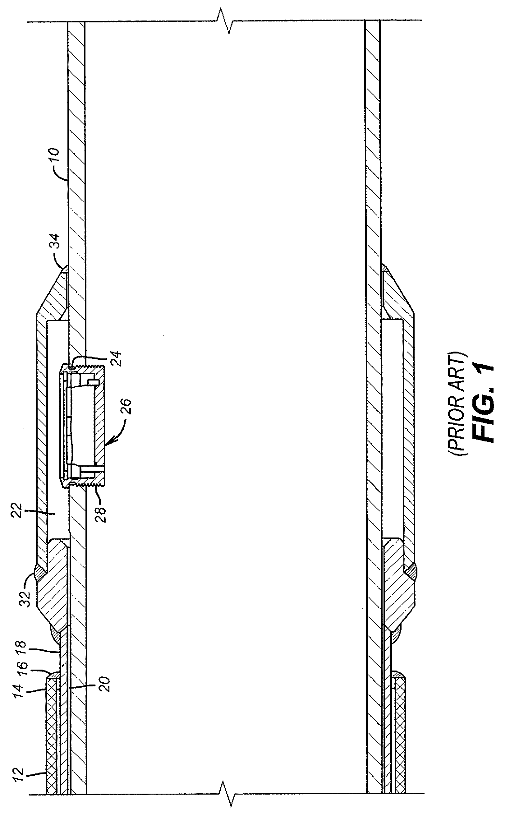
[0017]FIG. 1 illustrates a base pipe 10 with a cylindrically shaped screen 12 mounted over it and sealed at both ends although only one end is shown. At end 14 there is a continuous weld 16 to a ring 18 which includes a plurality of standoffs to define axially extending passages 20 that lead to annularly shaped chamber 22. One or more openings 24 are first placed in the base pipe 10 wall and threaded to accept valve assembly 26 at its thread 28. After the screen 12 is attached, as described, and the openings 24 created and tapped, the valve assembly 26 is screwed in and the sleeve 30 is put into position and continuously welded at top 32 and bottom 34. The valve illustrated in FIG. 1 has the capability to detect gas flow apart from liquid flow and close, or restrict, when gas flow is detected. Its internal workings are not a part of the present invention. This assembly technique is time consuming and expensive.

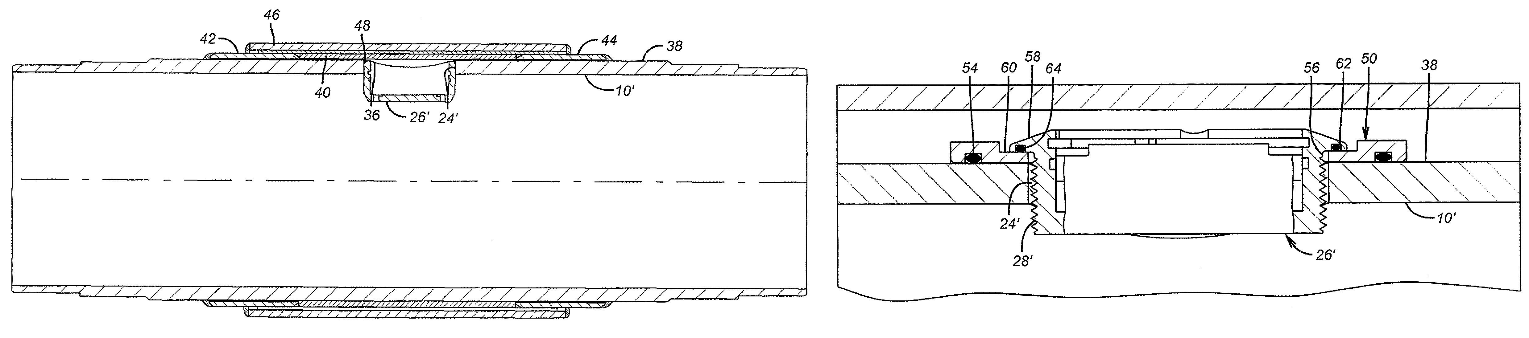
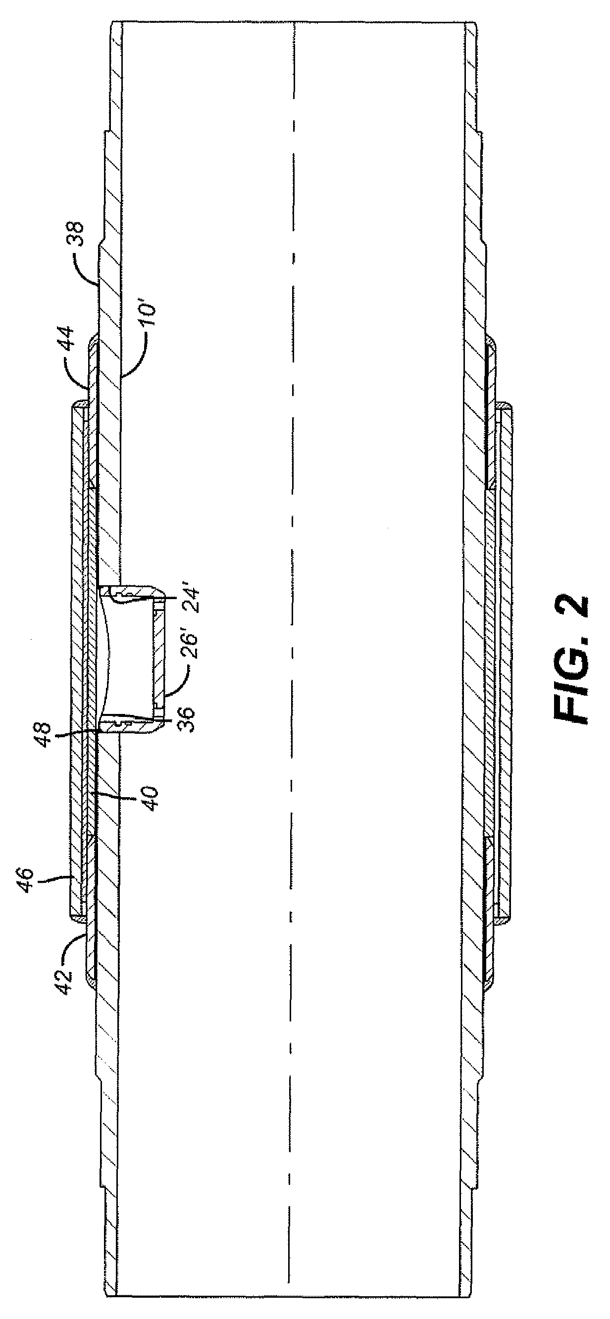
[0018]FIG. 2 shows a way to assemble the components more quickly and econ...


PUM


Abstract

In one aspect of the invention a valve that operates in association with a downhole screen is threaded into the wall of a base pipe after being inserted through a saddle. When the valve body is threaded in, the engagement into the wall threads in the base pipe acts as a sealing force on a ring seal between the saddle and the base pipe and between the valve body and the saddle. The valve itself can be outfitted with a cover with openings that can be integral or removable and disposed at the end of the valve that is innermost to the base pipe. Preferably a series of elongated slots are used that can catch slurry if the well is to be killed while allowing subsequent production to drive the accumulated solids from well killing back into the base pipe. Another feature places the valve in a base pipe opening under a cylindrical screen section to reduce assembly time and cost of constructing an adjacent housing to one side of the cylindrical screen section to accommodate the valve.

Description

FIELD OF THE INVENTION[0001]The field of the invention relates to downhole screens and more particularly to screens with valves in the base pipe and various mounting techniques for such valves.BACKGROUND OF THE INVENTION[0002]Screens are used downhole to hold back solids during production from a given productive zone. Such zones can be very long and can be in cased or open hole. In the past screen sections, which can be about 10 meters long are connected together to span the productive interval. In an effort to equalize flow along a long interval, individual screen sections have been outfitted with devices to resist flow in unequal amounts so as to insure flow that is reasonably uniform over the extended interval. Such screen sections are made by Baker Oil Tools under the brand Equalizer®. They feature an annular space between the cylindrical screen and an underlying base pipe. Once the flow gets through the screen it goes axially along the base pipe which has no openings under the ...

Claims


Application Information

Patent Timeline
Patent Type & Authority Patents(United States)
IPC IPC(8): E21B43/08
CPCE21B43/08E21B34/08E21B43/12E21B43/32
Inventor CORONADO, MARTIN P.CROW, STEPHEN L.HENRIKSEN, KNUT HERMAN
Owner BAKER HUGHES HLDG LLC
Why Eureka
Try Eureka