Fuel cell, fuel cartridge and fuel cell system

a fuel cell and cartridge technology, applied in the direction of cell components, instruments, packaged goods types, etc., can solve the problems of limited use of this fuel and its working place, and achieve the effect of improving safety, simple structure and constitution

Inactive Publication Date: 2010-01-12
NEC CORP
View PDF10 Cites 34 Cited by
  • Summary
  • Abstract
  • Description
  • Claims
  • Application Information

AI Technical Summary

Benefits of technology

[0009]The present invention has been made in view of the above situation and it is an object of the present invention to provide technologies for fitting a fuel cartridge filled with an adequate fuel to a fuel cell in a simple structure and constitution.
[0011]According to this construction, an inadequate fuel cartridge can be prevented from being mounted on the fuel cell since it can be discriminated whether an adequate fuel cartridge is mounted or not. This makes it possible to secure, for example, safety when the fuel cell is used.
[0012]In the fuel cell of the present invention, the identification part may include the fitting part that is selectively fitted into the fuel cartridge. Such a structure can prevent a fuel cartridge from being mounted on the fuel cell into which the fuel cartridge is not fitted.
[0013]In the fuel cell of the present invention, the identification part may include plurality of fitting parts and a selecting part that makes usable one fitting part to be selectively fitted into a specified fuel cartridge among these fitting parts. The selecting part may be, for example, a shutter that opens only one fitting part among these plurality of fitting parts and covers other fitting parts. The fitting part has a different shape or configuration corresponding to the type of fuel cartridge. Such a structure ensures that an any fitting part can be selected on the fuel cell side and it is therefore possible to mount an adequate fuel cartridge on the fuel cell depending on the environment and situation where the fuel cell is used.
[0026]According to this construction, an adequate fuel can be used in accordance with the working environment even in the situation where the use of the fuel is regulated, which makes it possible to improve safety.
[0027]According to the present invention as mentioned above, the fuel cell is provided with the identification part that identifies a fuel cartridge to be mounted and therefore, a fuel cartridge filled with adequate fuel can be fitted into the fuel cell in a simple structure and constitution.

Problems solved by technology

Also, in the case of using organic liquid fuel such as methanol, it is considered that the use of this fuel is limited by its working place.

Method used


Image

  • Fuel cell, fuel cartridge and fuel cell system
  • Fuel cell, fuel cartridge and fuel cell system
  • Fuel cell, fuel cartridge and fuel cell system

Examples


first embodiment

[0062]In this embodiment, a fuel cartridge is provided with a connecting part corresponding to fuel to be filled and a fuel cell is provided with a fitting part that fits to the connecting part of the fuel cartridge to mount a proper fuel cartridge.

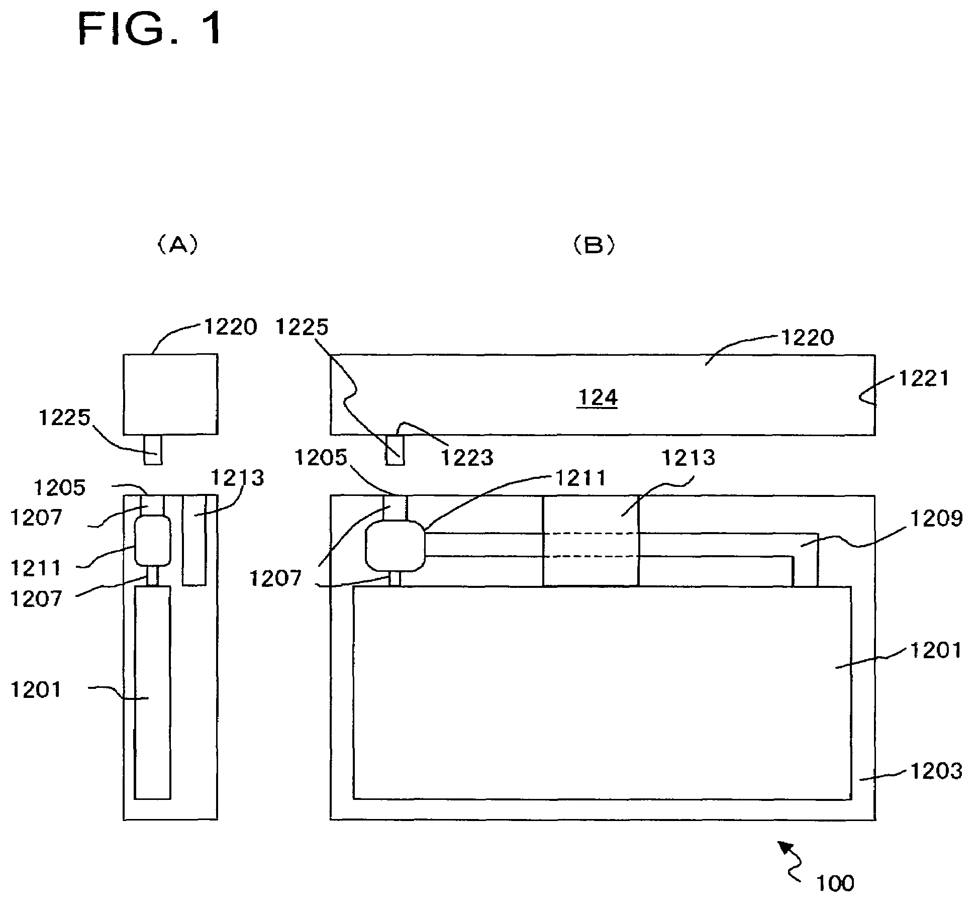
[0063]FIG. 1 is a view typically showing the construction of the fuel cell in this embodiment. FIG. 1(A) is a side arrangement drawing and FIG. 1(B) is a front arrangement drawing.

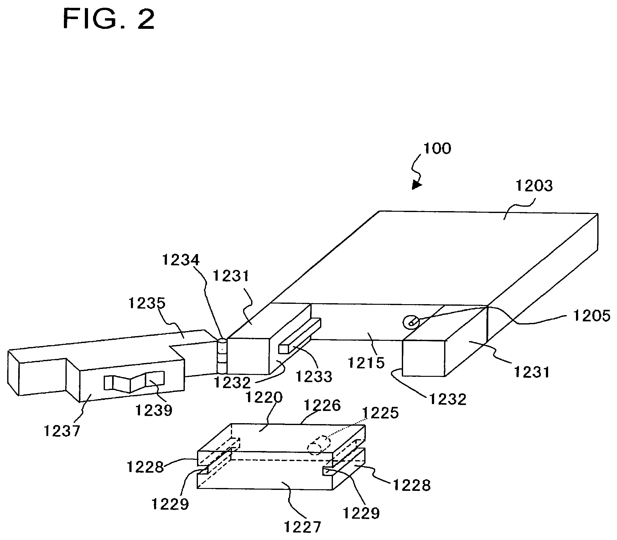
[0064]A fuel cell 100 is provided with a cell stack 1201 and a casing 1203 that receives the cell stack 1201. A fuel cartridge 1220 that receives a fuel 124 is fitted to the fuel cell 100. The fuel cartridge 1220 includes a fuel chamber 1221 receiving the fuel 124, an injection port 1223 which is opened into the fuel chamber 1221 and from which the fuel 124 is injected into the fuel cell 100 and a connecting part 1225 having a shape corresponding to the fuel 124 to be filled. Here, the connecting part 1225 is integrated with the injection port 1223.

[0065]The fue...

second embodiment

[0103]In this embodiment, the fuel cell 100 has a structure in which a proper fitting part can be selected so that a fuel cartridge filled with an adequate fuel can be selected depending on the working environment and situation.

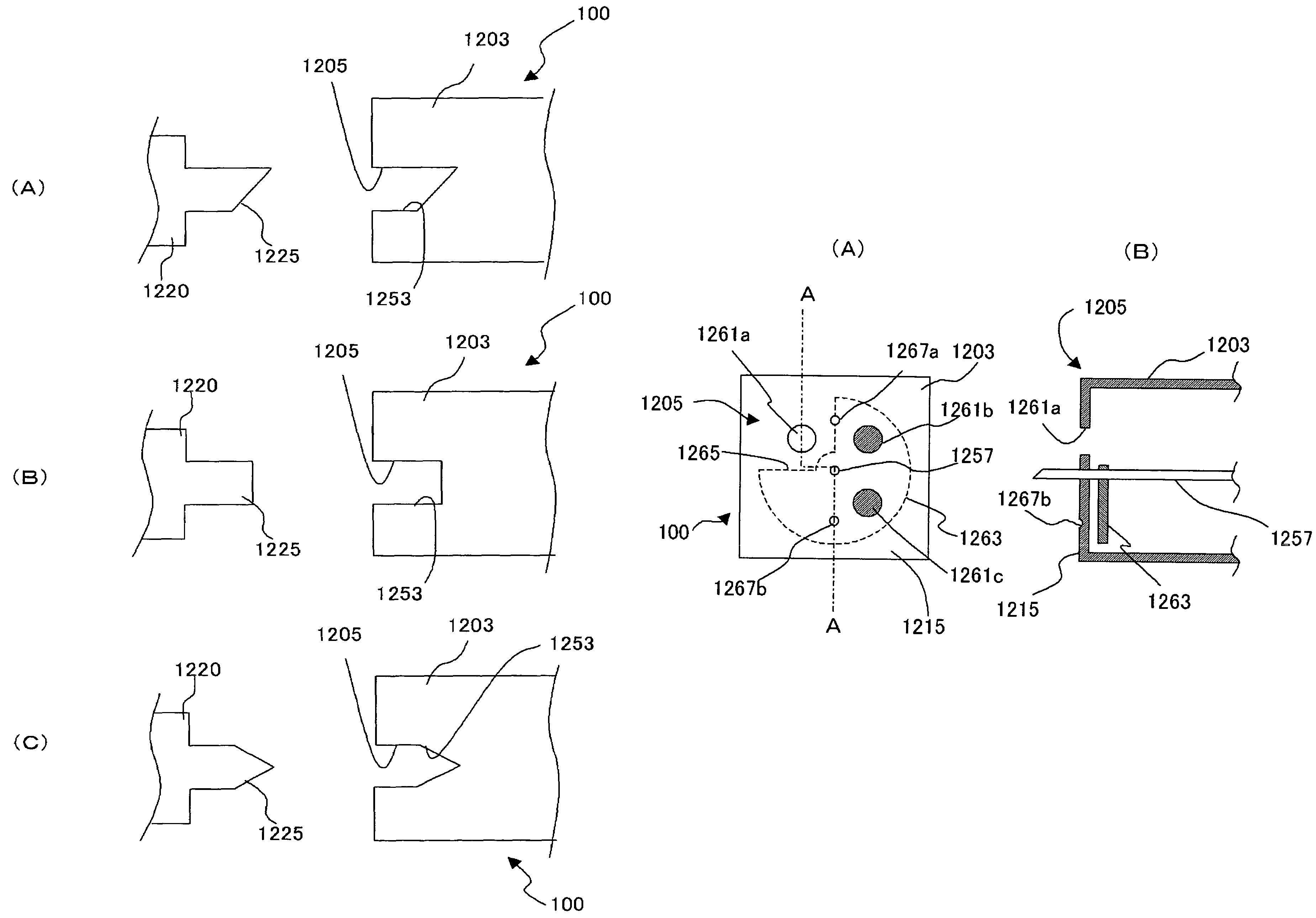
[0104]FIG. 11 is a view typically showing one example of the fitting part of the fuel cell in this embodiment, wherein FIG. 11(A) is a front view and FIG. 11(B) is a cross-sectional view taken along the line A-A in FIG. 11(A).

[0105]In this embodiment, plurality of receiving holes 1261a, 1261b and 1261c (three in FIG. 11), a shutter 1263 that opens only one of these receiving holes 1261a to 1261c and shuts the remaining holes, a hollow needle 1257, an alignment convex part 1267a and an alignment concave 1267b are provided on a receiving plane 1215 of a casing 1203 of the fuel cell 100. The shutter 1263 is provided on the backside or front side of the receiving plane 1215. Here, a structure in which the shutter 1263 is provided on the backside of the receiving ...

third embodiment

[0127]In this embodiment, the fuel cell 100 identifies the mounted fuel cartridge 1220 based on the condition of the electrical connection with the fuel cartridge 1220. Also, the fuel cell 100 detects the type of fuel contained in the mounted fuel cartridge 1220 and controls the operation condition depending on the type of fuel.

[0128]FIG. 20 is a view showing the fuel cell 100 and the fuel cartridge 1220 in this embodiment.

[0129]The fuel cartridge 1220 includes plurality of connecting terminals X1, X2, X3 and X4 and a terminal Z that selectively connects the connecting terminal X1 with any one of the connecting terminals X2, X3 and X4. The fuel cartridge 1220 is constructed so as to be able to select which one among the connecting terminals X2 to X4 to connect with the connecting terminal X1 depending on the type of fuel to be filled. Also, though it is assumed that the connecting terminal X1 is secured here, a structure may be adopted in which the fuel cartridge 1220 provided with ...


PUM

PropertyMeasurementUnit
electricalaaaaaaaaaa
depthaaaaaaaaaa
concentrationaaaaaaaaaa

Abstract

A fuel cell (100) is mounted with a fuel cartridge (1220) in a detachable manner. The fuel cartridge (1220) is provided with a connecting part (1225) and the fuel cell (100) is provided with a fitting part (1205) into which the connecting part (1225) is fitted. The fuel cell (100) identifies the fitted fuel cartridge (1220).

Description

TECHNICAL FIELD[0001]The present invention relates to a fuel cell, a fuel cartridge to be mounted on the fuel cell and a fuel cell system including them.BACKGROUND ART[0002]A fuel cells is comprised of a fuel electrode, an oxidant electrode and an electrolyte interposed between these electrodes, wherein fuel is supplied to the fuel electrode and an oxidizer is supplied to the oxidant electrode, to generate electricity by an electrochemical reaction of the fuel. Hydrogen is generally used as the fuel. In the meantime, a direct fuel cell that directly utilizes inexpensive and easily handlable methanol as the fuel has been enthusiastically developed in recent years.[0003]When hydrogen is used as the fuel, the reaction at the fuel electrode is as shown in the following equation (1).3H2→6H++6e−  (1)[0004]When methanol is used as the fuel, the reaction at the fuel electrode is as shown in the following equation (2).CH3OH+H2O→6H++CO2+6e−  (2)[0005]In all these cases, the reaction at the ox...

Claims


Application Information

Patent Timeline
Patent Type & Authority Patents(United States)
IPC IPC(8): H01M2/00B65D8/00B65D83/00B65D85/00H01M8/04B65D88/54H01M8/06
CPCH01M8/04208H01M8/1011Y02E60/50Y10T137/4673Y10T137/4757Y10T137/87925
Inventor AKIYAMA, EIJIKUBO, YOSHIMIYOSHITAKE, TSUTOMUMANAKO, TAKASHIKAJITANI, HIROSHIKIMURA, HIDEKAZUNAGAO, SATOSHIWATANABE, YOSHINORIKONO, YASUTAKA
Owner NEC CORP
Why Eureka
Try Eureka