Wiring harness fastening device for electric supply line of sliding door and electric supply system utilizing the same

a technology of electrical supply line and wiring harness, which is applied in the direction of cable arrangement between relatively moving parts, coupling device connections, cables, etc., can solve the problems of further reducing and achieve the effect of preventing further twisting, preventing further twisting of the wiring harness, and increasing the endurance of the wiring harness

Active Publication Date: 2010-01-12
YAZAKI CORP
View PDF11 Cites 34 Cited by
  • Summary
  • Abstract
  • Description
  • Claims
  • Application Information

AI Technical Summary

Benefits of technology

[0011]When the wiring harness fastening device is assembled to the vehicle body and the wiring harness is twisted, the protrusion of the rotational portion abuts to the rib of the case and prevents further twisting. When the wiring harness is further twisted while the protrusion abuts to the rib, a worker feels the reversed torsion of the wiring harness with his hand and adjusts the twisting when assembling so that the wiring harness after assembly does not have an excess torsion. When the sliding door is slammed after assembly, the protrusion abuts to the rib and prevents further twisting of the wiring harness. According to a second aspect of the present invention, the wiring harness fastening device has a circular-shaped rib intersecting with the rib for slidably holding the rotational portion.
[0012]Thereby, the rotational portion can rotate smoothly in the case. Thus, when the wiring harness is assembled to the vehicle body, the rotational portion rotates smoothly to absorb the twisting of the wiring harness and assists the protrusion to abut the rib.
[0014]Thereby, when the sliding door is opened and closed, the wiring harness swings with the rotational portion and is wound along the wiring harness guide wall of the case so that the wiring harness is prevented from bending and the endurance thereof is improved.
[0016]Thereby, when the sliding door is opened and closed strongly, the protrusion of the rotational portion does not hit strongly the rib of the case so that the wear and damage with time of the protrusion and the rib are prevented.
[0018]Thereby, the wiring harness is arranged from the fastening device to the sliding door and can rotate in a circumferential direction thereof and wind up-and-down and right-and-left with the rotational portion. When the sliding door is opened and closed and the wiring harness swings, twists and winds, the rotational portion absorbs the twisting and winding of the wiring harness with the rotation and winding thereof. When the fastening device is assembled to the vehicle body and the wiring harness is twisted, the protrusion of the rotational portion abuts to the rib of the case and prevents further twisting. When the wiring harness is further twisted while the protrusion abuts to the rib, a worker feels the reversed torsion of the wiring harness with his hand and adjusts the twisting when assembling so that the wiring harness after assembly does not have an excess torsion. When the sliding door is slammed after assembly, the protrusion abuts to the rib and prevents further twisting of the wiring harness. Excess twisting and winding force do not act to the wiring harness so that the endurance of the wiring harness becomes higher.

Problems solved by technology

When the fastening device is assembled to the vehicle body and the wiring harness is twisted, the wiring harness further decreases the endurance when the sliding door is opened and closed.

Method used


Image

  • Wiring harness fastening device for electric supply line of sliding door and electric supply system utilizing the same
  • Wiring harness fastening device for electric supply line of sliding door and electric supply system utilizing the same
  • Wiring harness fastening device for electric supply line of sliding door and electric supply system utilizing the same

Examples


Embodiment Construction

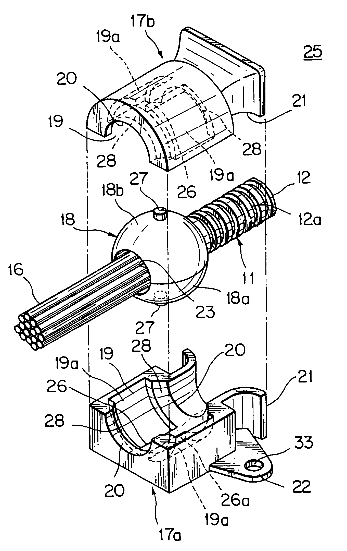
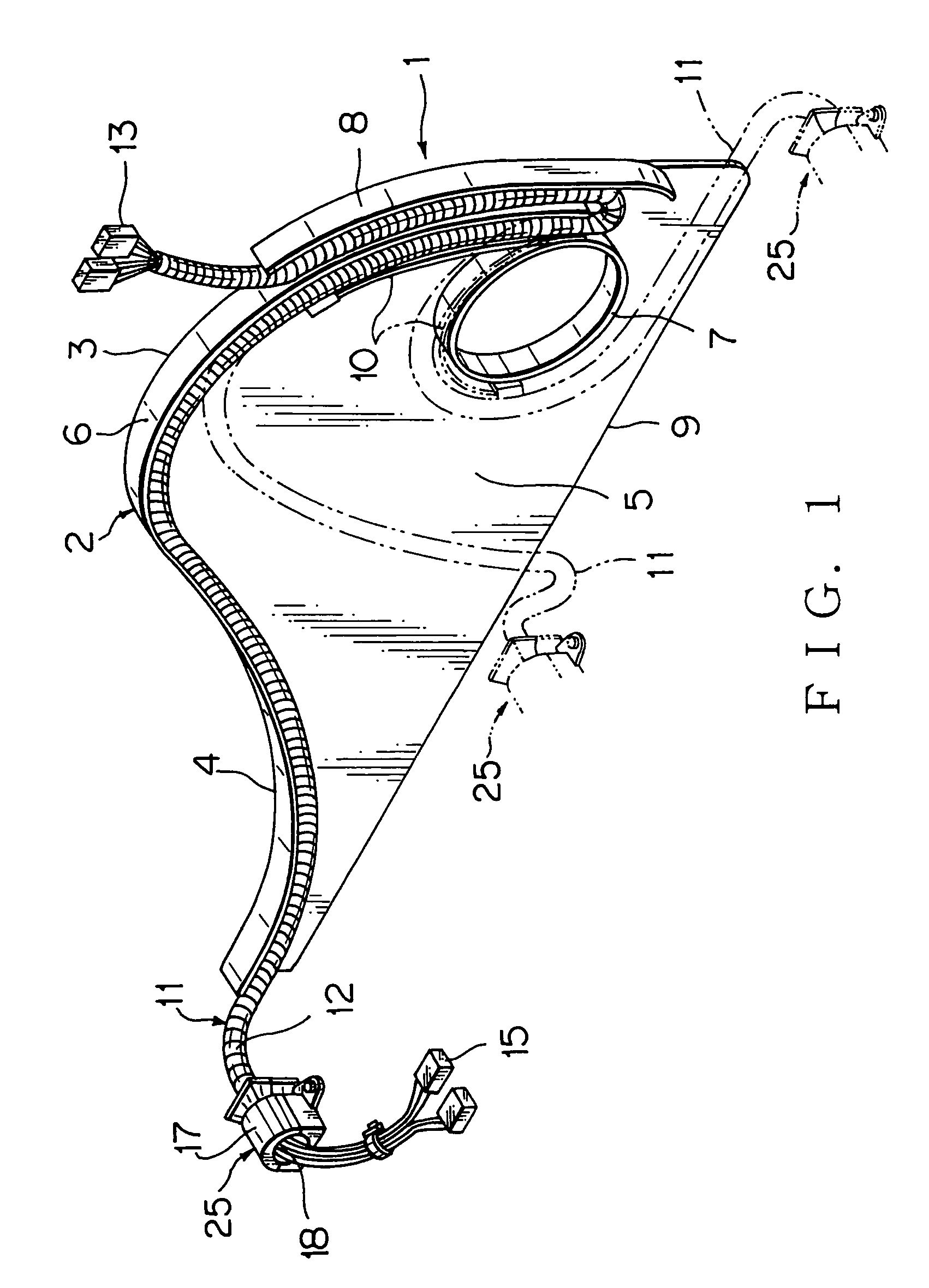
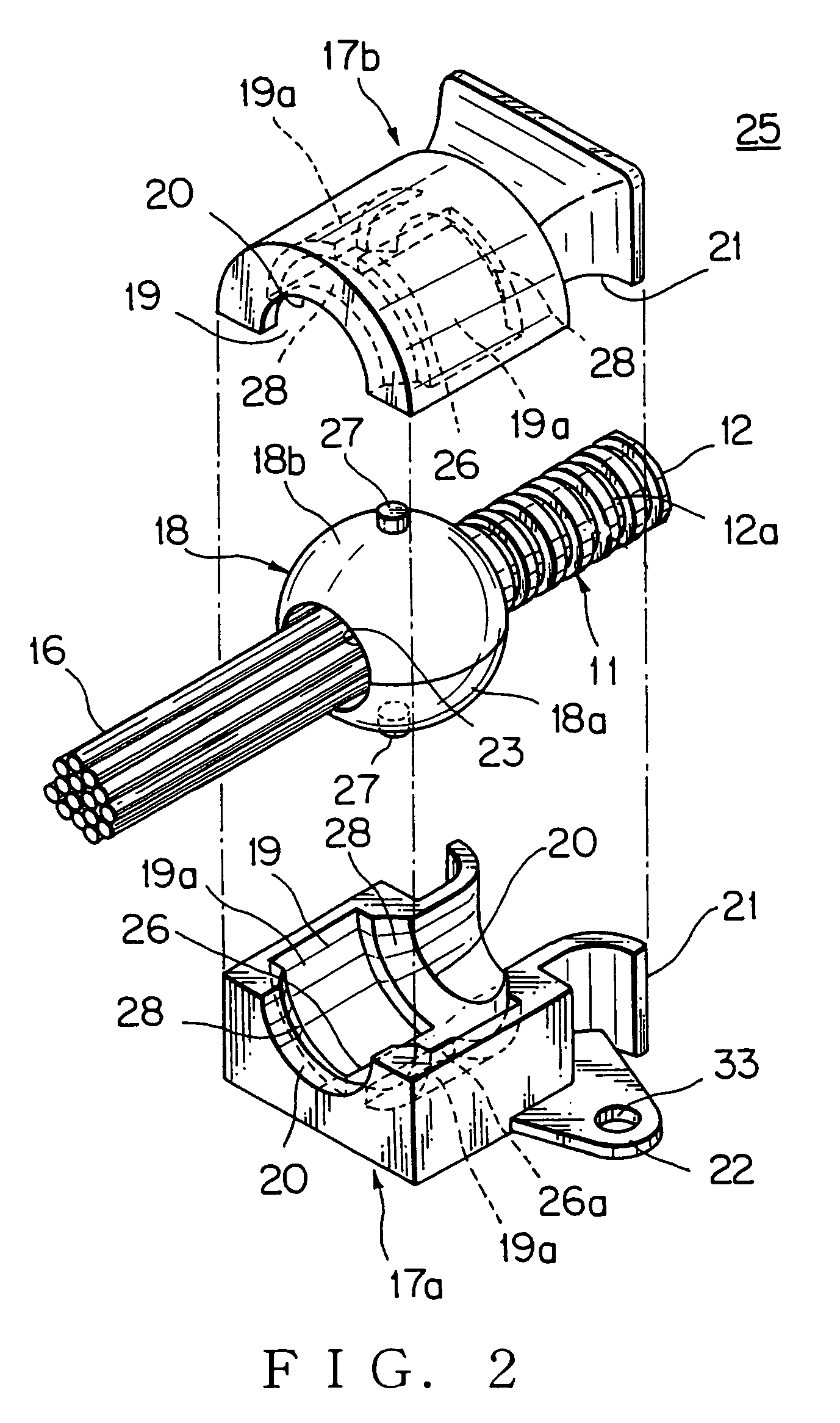
[0023]Embodiments of the present invention are explained by referring to drawings. FIG. 1 shows an embodiment of a electric supply system utilizing a wiring harness fastening device for a sliding door. FIG. 2 is an embodiment of the wiring harness fastening device.

[0024]A wiring harness protector 1, hereafter referred to protector, made of a synthetic resin, has a protector main body 2, a cover (not shown), a semicircular portion 3, and an extended portion 4 with a varying height following from the semicircular portion 3.

[0025]The protector main body 2 includes a vertical base plate 5, a curved wall 6, an annular regulating wall 7 disposed forward the base plate 5, and a upwardly curved wiring harness lead-out 8 disposed outside the curved wall 6. The protector main body 2 has an elongated opening 9 at a bottom thereof for leading out the wiring harness. The cover, not shown, is fixed to the protector main body 2 with locking means such as flexible locking claws or holes, not shown....


PUM


Abstract

The present invention is to prevent twisting of a wiring harness when it is assembled to a vehicle. A wiring harness fastening device for an electric supply line of a sliding door includes a rotational portion having a spherical shape for fastening the wiring harness and a case having a spherical receiving space for rotatably holding the rotational portion, wherein the rotational portion has a protrusion at an outer surface thereof, wherein the receiving space has a rib, and wherein the protrusion abuts to the rib when the wiring harness is twisted. The rotational portion has a circular-shaped rib intersecting with the rib for holding the rotational portion slidably. The case has a wiring harness guide wall with a curved shape to lead out the wiring harness. The wiring harness abuts the wiring harness guide wall prior to the protrusion abuts the rib.

Description

TECHNICAL FIELD[0001]The present invention relates to a wiring harness fastening device for an electric supply line of a sliding door of motor vehicles such as station wagons, and for absorbing twisting or winding of the wiring harness when the sliding door is closed and opened, and also relates to an electric supply system utilizing the same.RELATED ART[0002]As shown in FIG. 4, a wiring harness 70 with a plurality of electric wires is arranged from a body of a motor vehicle to a sliding door 71 to supply electric current or signal current to auxiliary units such as electric components in the sliding door. The wiring harness 70 is received in a protector 72, made of a synthetic resin, in the sliding door 71. An electric supply system for adjusting winding of the wiring harness 70 responding to the opening and closing of the sliding door 71 is disclosed, for example, JP-2001-354085-A.[0003]The auxiliary units, such as power window motors, door locking units, switch units and opening ...

Claims


Application Information

Patent Timeline
Patent Type & Authority Patents(United States)
IPC IPC(8): H02G3/04B60L5/38H02G5/04H01R33/00B60R16/02F16L3/10H02G3/30H02G3/38H02G11/00
CPCB60R16/0215H02G3/0468H02G3/30H02G11/006
Inventor KOGURE, NAOTOSANADA, HIROSHI
Owner YAZAKI CORP
Why Eureka
Try Eureka