Conversion method, apparatus and computer program for converting a digital image obtained by a scanner

a conversion method and digital image technology, applied in the field of image conversion methods, can solve problems such as noise in digital images obtained by scanning units, and achieve the effect of improving the quality of the converted images and reducing the speckling

Inactive Publication Date: 2010-01-12
OCE TECH
View PDF12 Cites 0 Cited by
  • Summary
  • Abstract
  • Description
  • Claims
  • Application Information

AI Technical Summary

Benefits of technology

[0007]The object of the present invention is to improve an image conversion method of the above type such that the speckling effect is reduced and the quality of the converted images is improved.
[0010]With the method of the present invention, a wrong selection for conversion of some noisy pixels present in substantially uniform colored areas is avoided. In such an area, the representative color distance determined between a number of pixels located in a vicinity of the target pixel in the digital image and the background color is generally more than a predefined threshold value. In such case, a noisy pixel is not selected for conversion, even if its color is close to the background color. The results obtained are better than when the selection is based only on the color of the isolated target pixel. Experiments have indeed shown that it is better to leave a noisy pixel in a substantially uniform colored area to its original colorimetric values than to convert it to white (or to an intermediate value).
[0012]Thanks to the fact that noisy pixels in uniform colored areas are not selected for conversion, while noisy pixels in background areas are selected for conversion, the speckling effect in converted digital images is strongly reduced, and the quality of the digital images is greatly enhanced.
[0013]In one embodiment of the method according to the present invention, the representative color distance is the averaged squared distance between a number of pixels located in the vicinity of the target pixel and the background color. That way, the representative color distance can be determined easily and leads to good results. Preferably, the representative color distance is determined in a perceptual color space.

Problems solved by technology

Most of the time, noise is present in digital images obtained by a scanning unit.

Method used


Image

  • Conversion method, apparatus and computer program for converting a digital image obtained by a scanner
  • Conversion method, apparatus and computer program for converting a digital image obtained by a scanner
  • Conversion method, apparatus and computer program for converting a digital image obtained by a scanner

Examples


Embodiment Construction

[0026]Preferred embodiments of the present invention will now be described with reference to the accompanying drawings, wherein the same or similar elements will be identified with the same reference numerals.

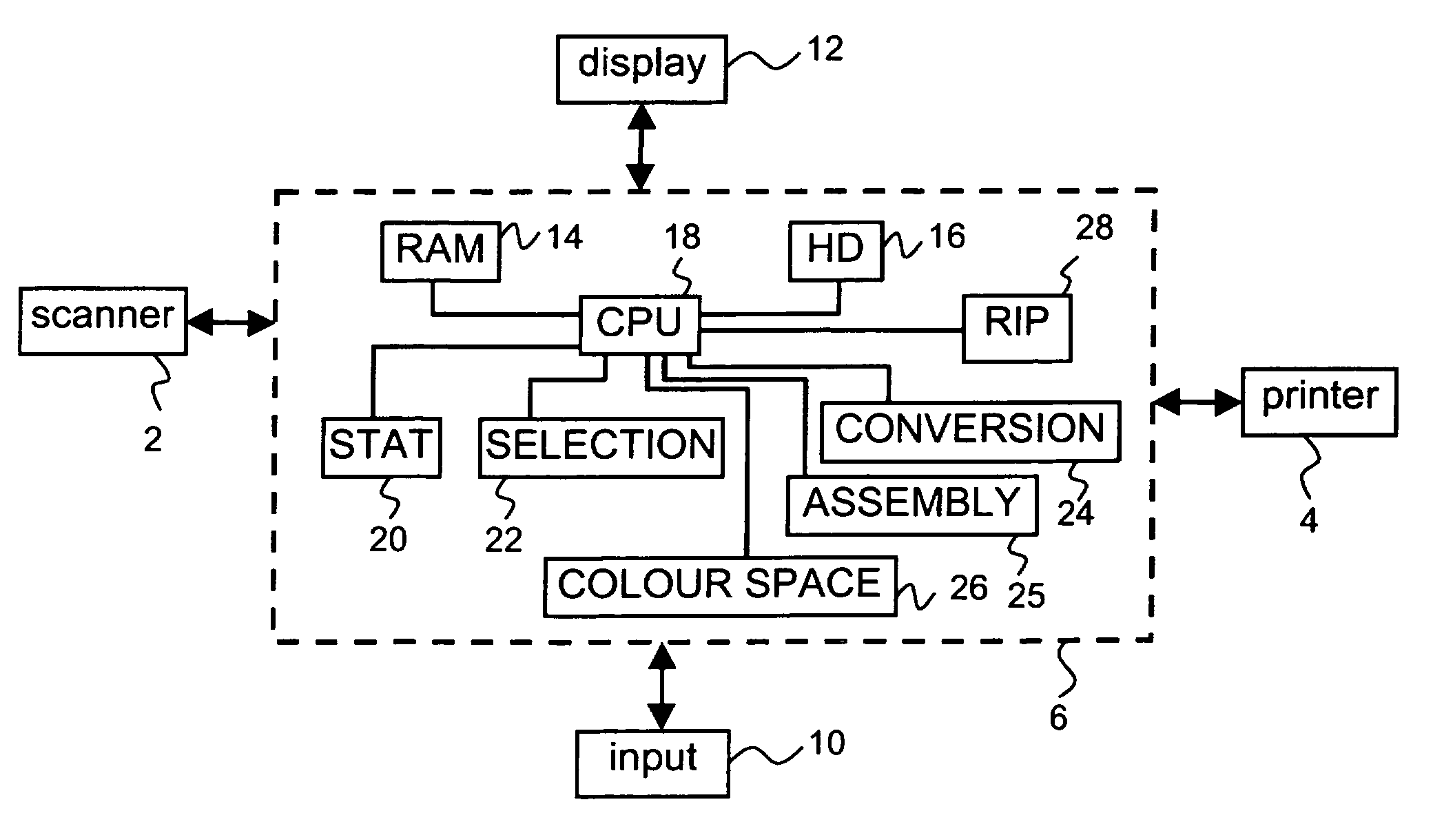
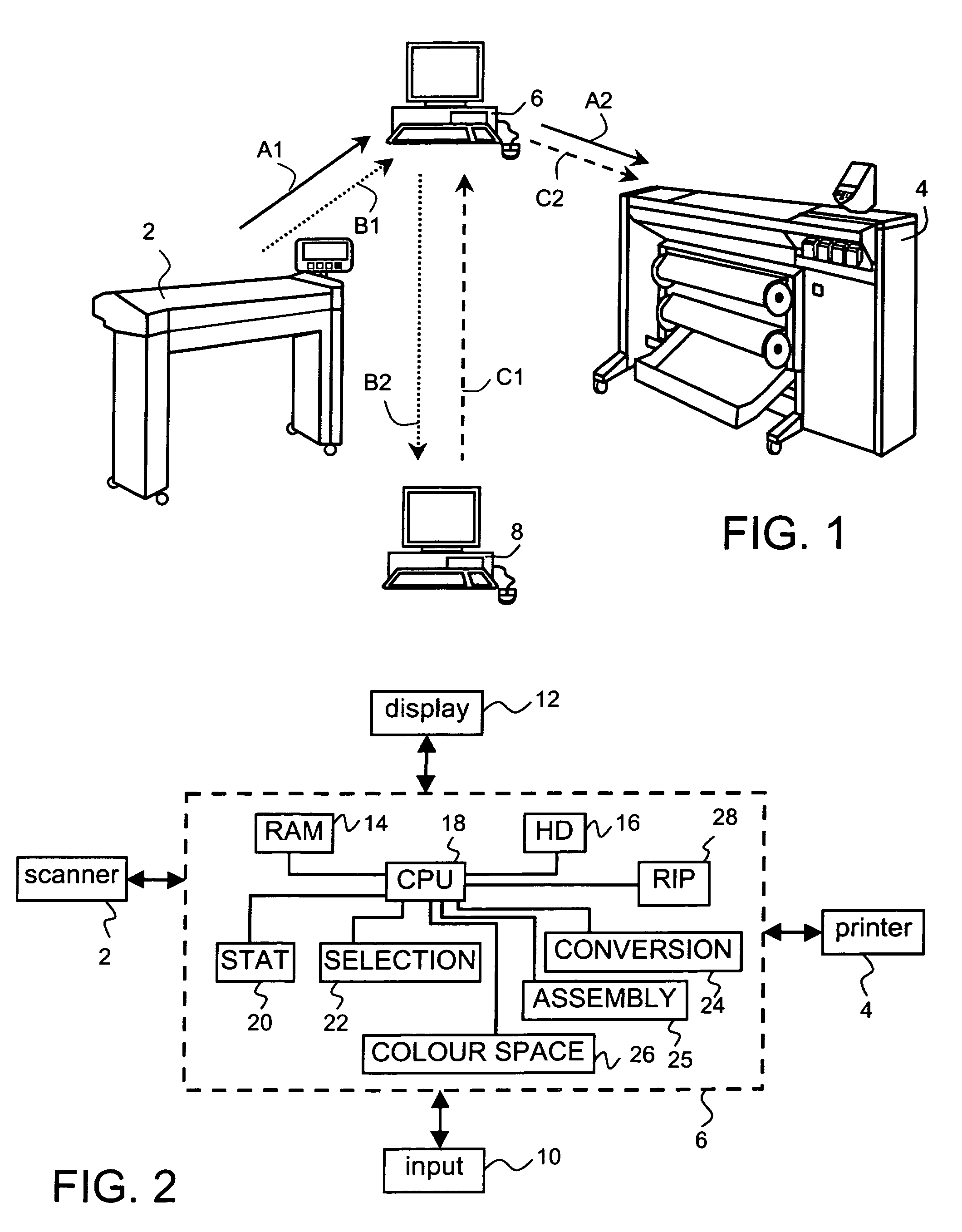
[0027]The image conversion method for converting a digital image obtained by a scanning unit into a converted digital image according the present invention may be used in an environment as shown in FIG. 1. A scanning unit 2 is provided for scanning an original color document supported on a support material. The scanning unit 2 is provided with an exposure unit (not shown) for illuminating an original document placed on a glass cover (not shown). A reflecting and guiding unit (not shown) is used for allowing the light which is reflected from the document to be directed towards a CCD type color image sensor (i.e. a photoelectric conversion device) which converts the reflected light into electric signals corresponding to the primary colors red (R), green (G) and blue (B).

[0028]A p...


PUM


Abstract

An image conversion method and an apparatus for converting a digital image obtained by a scanning unit into a converted digital image includes the steps of acquiring statistics for at least some pixels of the digital image, extracting characteristic values of a background color using the acquired statistics, operating a selection of pixels in the digital image, and converting the selected pixels. Each pixel in the digital image is sequentially set as a target pixel, and the selection of the target pixel depends on a representative color distance determined between a number of pixels located in a vicinity of the target pixel and the background color.

Description

CROSS-REFERENCE TO RELATED APPLICATIONS[0001]This nonprovisional application claims priority under 35 U.S.C. § 119(a) on Patent Application No. 05291732.5, filed in Europe on Aug. 16, 2005, the entirety of which is incorporated herein by reference.BACKGROUND OF THE INVENTION[0002]1. Field of the Invention[0003]The present invention relates to an image conversion method for converting a digital image obtained by a scanning unit into a converted digital image. The image conversion method includes the steps of acquiring statistics for at least some pixels of the digital image, extracting characteristic values of a background color using the acquired statistics, operating a selection of pixels in the digital image, each pixel in the digital image being sequentially set as a target pixel, and converting the selected pixels.[0004]2. Description of Background Art[0005]Documents to be scanned often have large portions of non-marked areas representing the background of the image. However, wh...

Claims


Application Information

Patent Timeline
Patent Type & Authority Patents(United States)
IPC IPC(8): G06K9/00G06K9/32H04N1/60
CPCG06T7/0081H04N1/58G06T2207/10008G06T2207/10024G06T7/11
Inventor MALIK, JULIENMICHON, FREDERIC L. M. J.
Owner OCE TECH
Why Eureka
Try Eureka