
Method and device for processing a wire

a processing device and wire technology, applied in the direction of textile cables, electrical appliances, textile treatment untwisting devices, etc., can solve the problems of contactless wires of longer length that are taken out of the machine in bundled state, too high cost, and negative twisting in the wir

Active Publication Date: 2010-01-19
KOMAX HOLDING
View PDF12 Cites 15 Cited by
  • Summary
  • Abstract
  • Description
  • Claims
  • Application Information

AI Technical Summary

Benefits of technology

[0015]The present invention provides a remedy to and avoids the disadvantages of the known machines with a method and a device that counteract the formation of twist in a wire.
[0016]The advantages achieved by the present invention are mainly that with the manufacture of wire bundles without doubled-back loops, the production time especially for subsequent processing processes can be substantially reduced. Furthermore, only with twist-free wire-processing processes, do for example wire connections manufactured by ultrasonic methods become possible. Cable bundles that do not need to be untangled manually after they have been manufactured are of higher quality since the individual wires have no kinks or knots and can therefore be better laid. Furthermore, with mechanical removal of the wire twist, wire bundles that are free of doubled-back loops can always be guaranteed.

Problems solved by technology

Active driving or rotation of the cable drums would be too cost-intensive, especially since different intermittent wire processes would make costly controlled wire stores necessary as compensation (see FIG. 9).
The twist in the wire manifests itself negatively particularly if the wire-ends are fitted with contacts that are not fitted in housing compartments in a 1:1 sequence.
Even contactless wires of longer length that are taken out of the machine in bundled state tend to twist.
The consequence is tangled wire in the wire bundle that also has to be untangled manually.
If a wire with the aforesaid characteristics is now pulled through a straightening track of a wire-processing machine, the tensions of the individual wire strands can change and thereby greatly affect the overall twist (drum, wire) as a result of overlaying.

Method used


Image

  • Method and device for processing a wire
  • Method and device for processing a wire
  • Method and device for processing a wire

Examples


Embodiment Construction

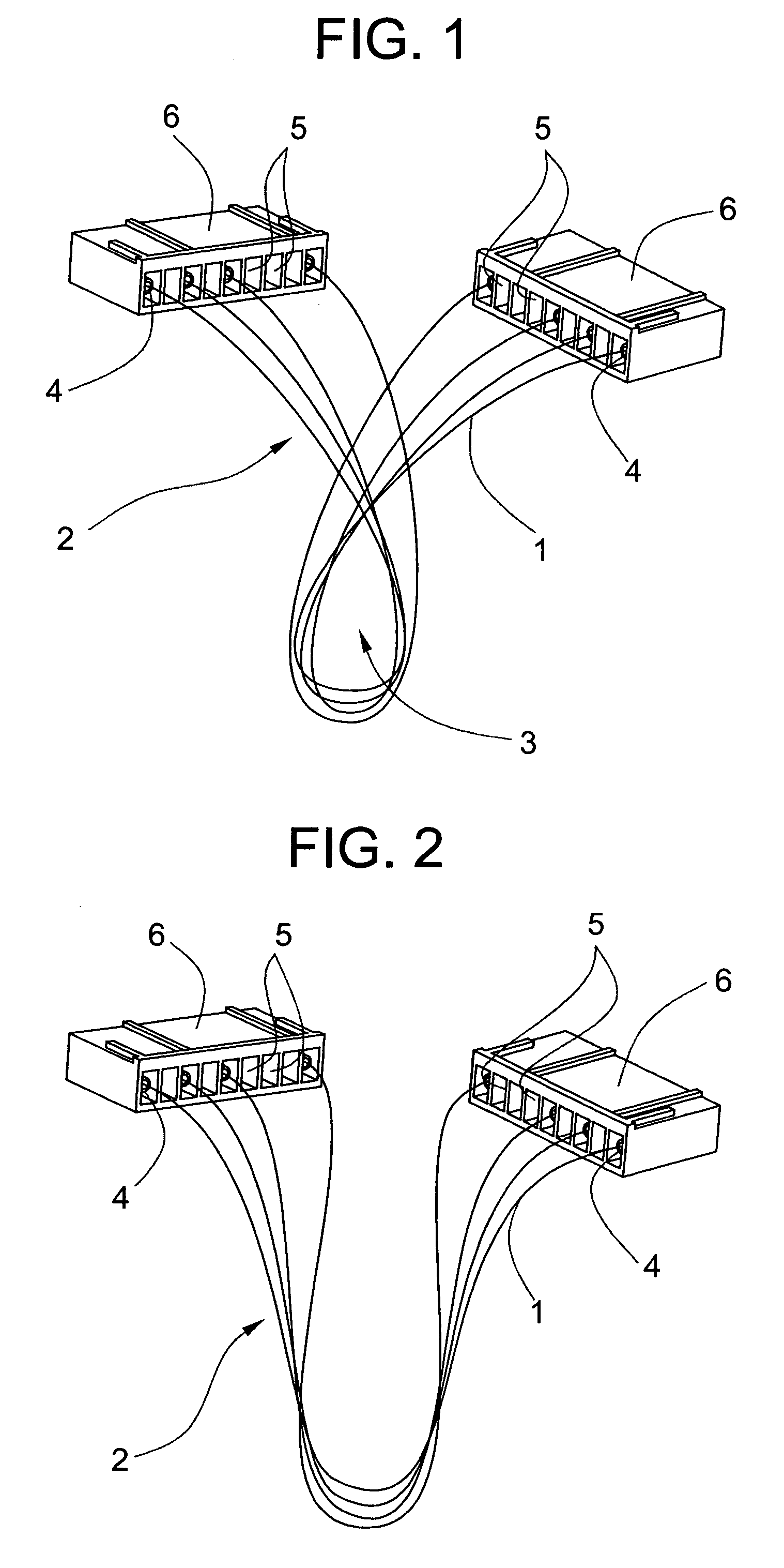
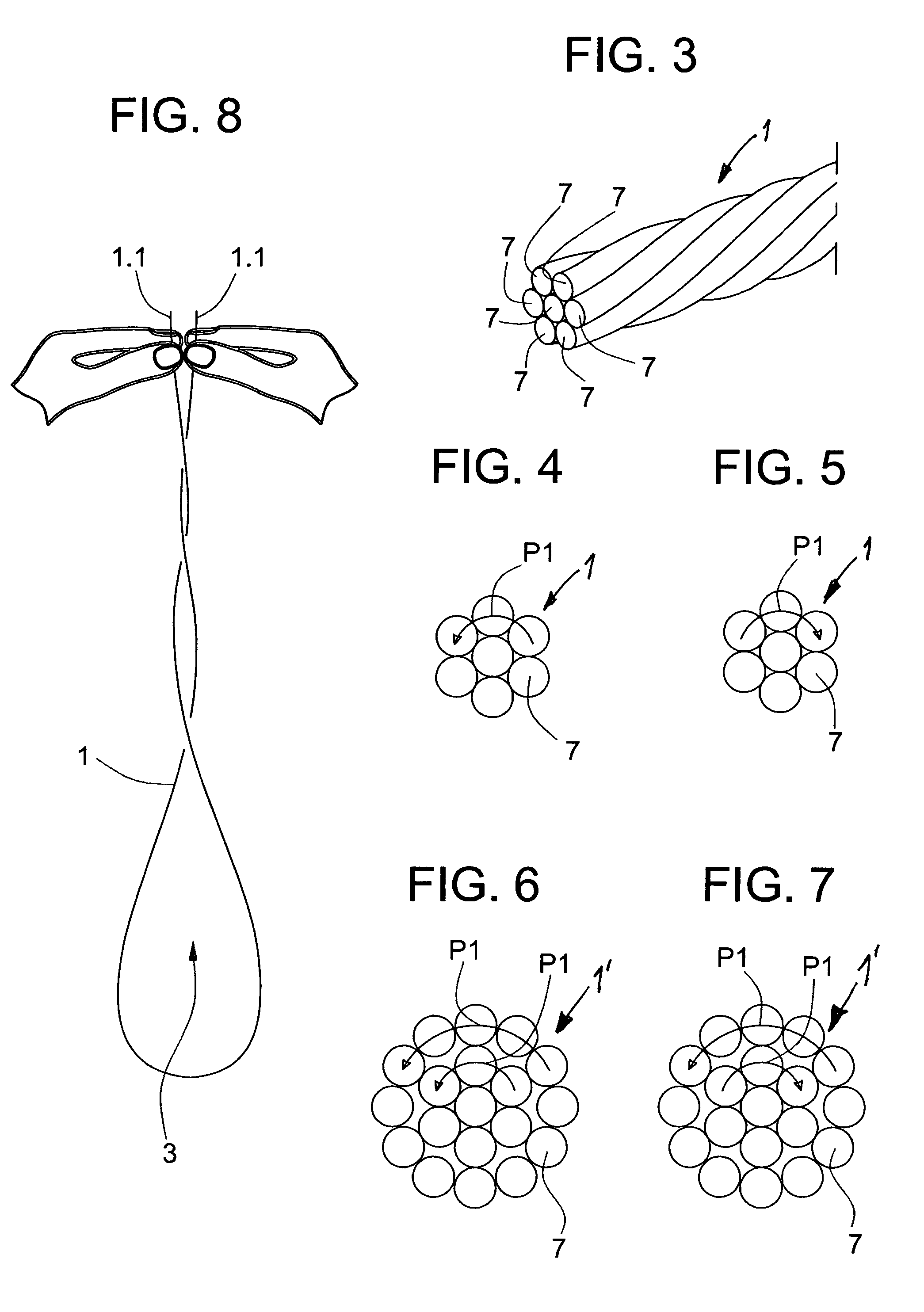
[0029]FIG. 1 shows a wire bundle 2 comprising several wires 1 with doubled-back loops 3 caused by wire twist. Arranged on the wire-ends are, for example, are contacts 4 engaging compartments 5 of connector housings 6. While being processed (having its end cut off, insulation stripped, bush mounted, contact crimped, etc.) each wire 1 is held at both wire-ends 1.1 (FIG. 8) so that in the manner described above the twist could not relax and cause the doubled-back loops 3. FIG. 2 shows the wire bundle 2 with untwisted wires 1 and with no doubled-back loops 3. After the wires 1 have been cut to length, they are mechanically untwisted around their longitudinal axis and can therefore not form any further doubled-back loops 3.

[0030]FIGS. 3 to 7 show the stripped wire 1 with laid strands 7 as electric conductors and their lay. FIGS. 3 to 5 show the wire 1 with seven of the strands 7. FIGS. 6 and 7 show a wire 1′ with nineteen of the strands 7. The type of lay (left-hand or right-hand lay) is...


PUM

PropertyMeasurementUnit
diameteraaaaaaaaaa
diameteraaaaaaaaaa
lengthaaaaaaaaaa

Abstract

In a wire-processing device, the wire executes turns through being pulled out of a drum. The leading wire-end is held by a gripper of a loop-former. A wire that has been cut to length is held at its leading and trailing ends by an untwisting unit, the wire having before the untwisting operation a doubled-backed loop. A transfer unit takes the leading and trailing ends from the loop-former and passes the wire to the untwisting unit. After the untwisting operation, the transfer unit feeds the wire-ends to the processing units that process the wire-ends. A bundling unit takes the processed wires from the transfer unit, the bundling unit forming a wire bundle with the wires. With the untwisted wires, the wire bundle has neither doubled-back loops nor knots.

Description

BACKGROUND OF THE INVENTION[0001]The present invention relates to a method and a device for processing a wire that is held at its ends.[0002]After a wire is manufactured, in many cases the wire is fed into a rotating drum. Such a wire drum may contain wire lengths of up to several thousands of meters and can weigh up to about eighty kilograms.[0003]In fully automatic wire-processing, the desired length of wire is pulled out of the top of the non-rotating wire drum by means of grippers and / or belt drives or roller drives.[0004]Normally, wire-processing devices are fed with different types of wire from several wire drums which can be selected and changed according to need by programmed control. Active driving or rotation of the cable drums would be too cost-intensive, especially since different intermittent wire processes would make costly controlled wire stores necessary as compensation (see FIG. 9).[0005]If, when the wire is pulled out of the wire drum, the wire cannot turn or relax...

Claims


Application Information

Patent Timeline
Patent Type & Authority Patents(United States)
IPC IPC(8): D07B7/18
CPCH01R43/28
Inventor BRAUN, ALFREDMEREDITH, ZANEBUCHER, WERNER
Owner KOMAX HOLDING
Learn More