Pressure-based fluid flow sensor
- Summary
- Abstract
- Description
- Claims
- Application Information
AI Technical Summary
Benefits of technology
Problems solved by technology
Method used
Image
Examples
examples
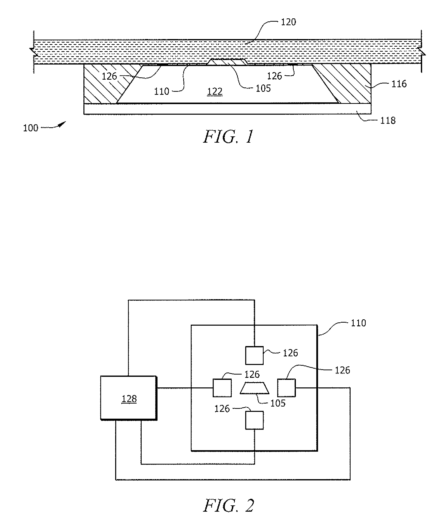
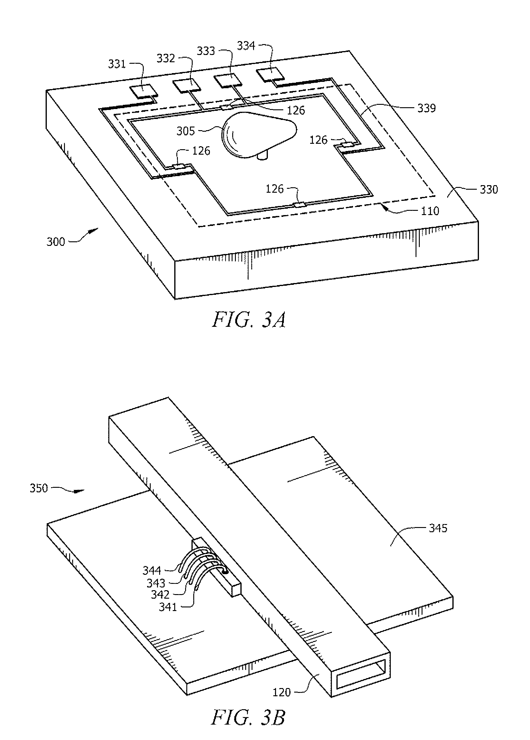
[0034]The examples provided below are non-limiting examples provided to only show particular embodiments of the present invention. Unless noted otherwise, the fluid was air and, the air flow was 1 m / sec, and the diaphragm was a silicon diaphragm 16 μm thick, and had a length and width of 1.7 mm. The sensing structure comprised piezoresistors. Simulations used Ansys software (Ansys, Inc. 275 Technology Drive Canonsburg, Pa. 15317. Reference data was generated by simulating air flow over a conventional flat diaphragm.
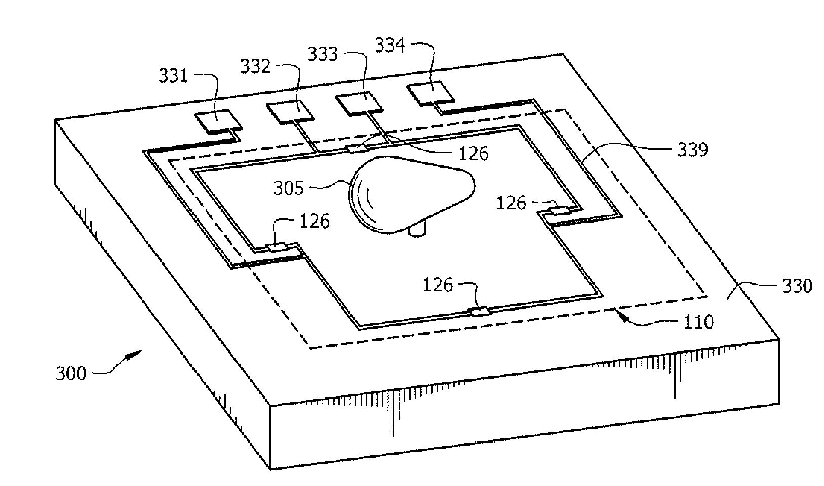
[0035]FIGS. 6A and B show the diaphragm deflection and Von Mises stress produced by the air flow, respectively. FIGS. 7A and B show the diaphragm deflection and Von Mises stress produced by the air flow over a diaphragm with a bump according to an embodiment of the invention. The dimensions of the bump were 600 μm width (in the flow direction), 250 μm length (perpendicular to the flow direction) and 100 μm height. The flow around the bump produces a larger pressure in thi...
PUM
 Abstract
Description
Claims
Application Information
 - R&D
- Intellectual Property
- Life Sciences
- Materials
- Tech Scout
- Unparalleled Data Quality
- Higher Quality Content
- 60% Fewer Hallucinations
Browse by: Latest US Patents, China's latest patents, Technical Efficacy Thesaurus, Application Domain, Technology Topic, Popular Technical Reports.
© 2025 PatSnap. All rights reserved.Legal|Privacy policy|Modern Slavery Act Transparency Statement|Sitemap|About US| Contact US: help@patsnap.com


