Leaning vehicle with tilting front wheels and suspension therefor

a front wheel and steering wheel technology, applied in the direction of vehicle springs, vehicle body stabilisation, vehicle springs, etc., can solve the problems of difficult to employ a larger vehicle, the type of suspension is difficult to employ, and the angle to which the vehicle frame can lean is limited

Active Publication Date: 2010-01-19
BOMBARDIER RECREATIONAL PROD INC
View PDF11 Cites 125 Cited by
  • Summary
  • Abstract
  • Description
  • Claims
  • Application Information

AI Technical Summary

Benefits of technology

[0007]Thus, there exists a need for a leaning vehicle having a two-wheel front suspension assembly that permits tilting of the wheels

Problems solved by technology

This suspension system is bulky and complex and it is specifically designed for two front wheels that are relatively close to one another.
This type of suspension would be difficult to employ on a larger vehicle in which the wheels are farther apart.
This type of front suspension with the appropriate tilting connections allows the wh

Method used


Image

  • Leaning vehicle with tilting front wheels and suspension therefor
  • Leaning vehicle with tilting front wheels and suspension therefor
  • Leaning vehicle with tilting front wheels and suspension therefor

Examples


first embodiment

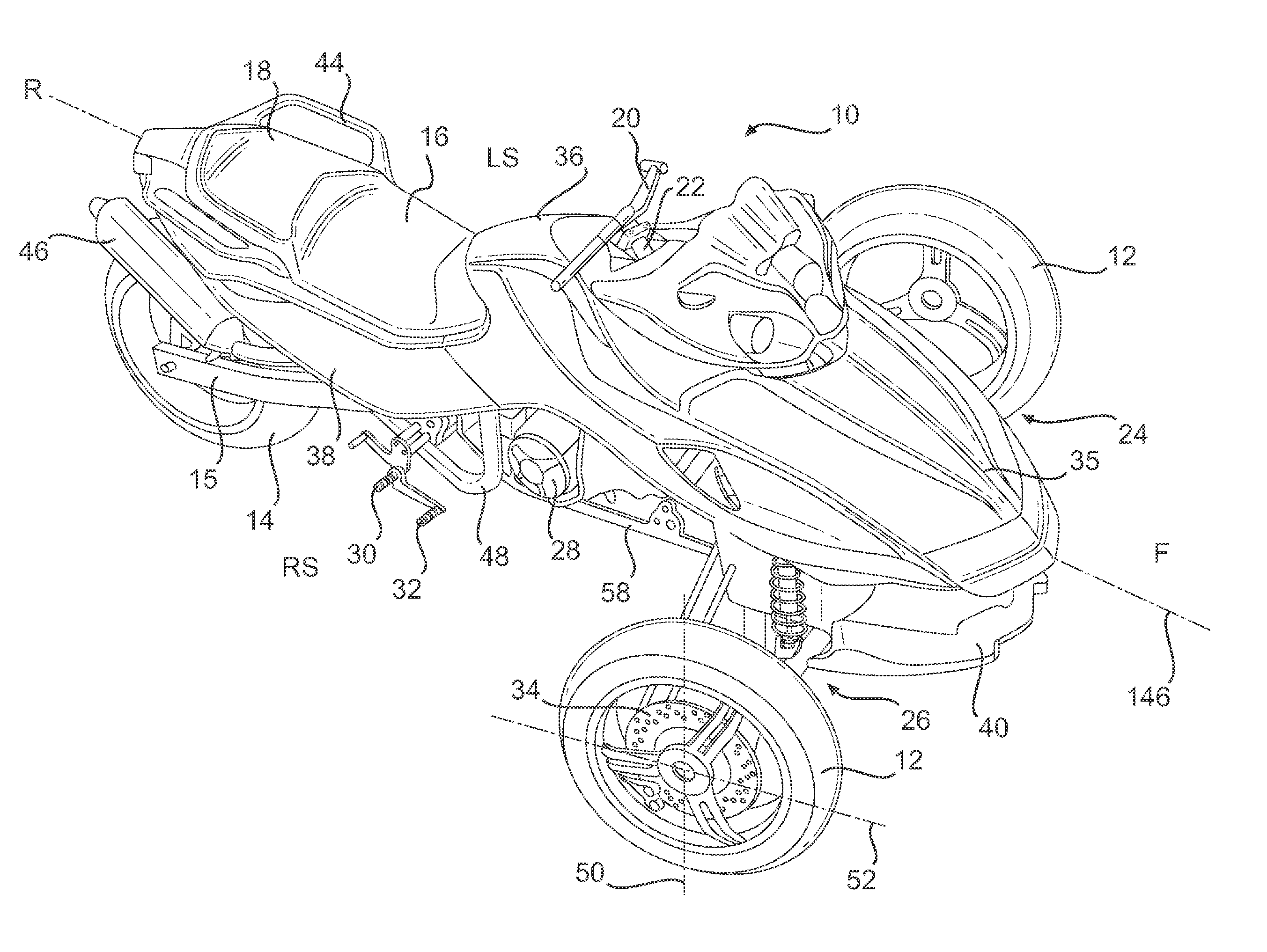
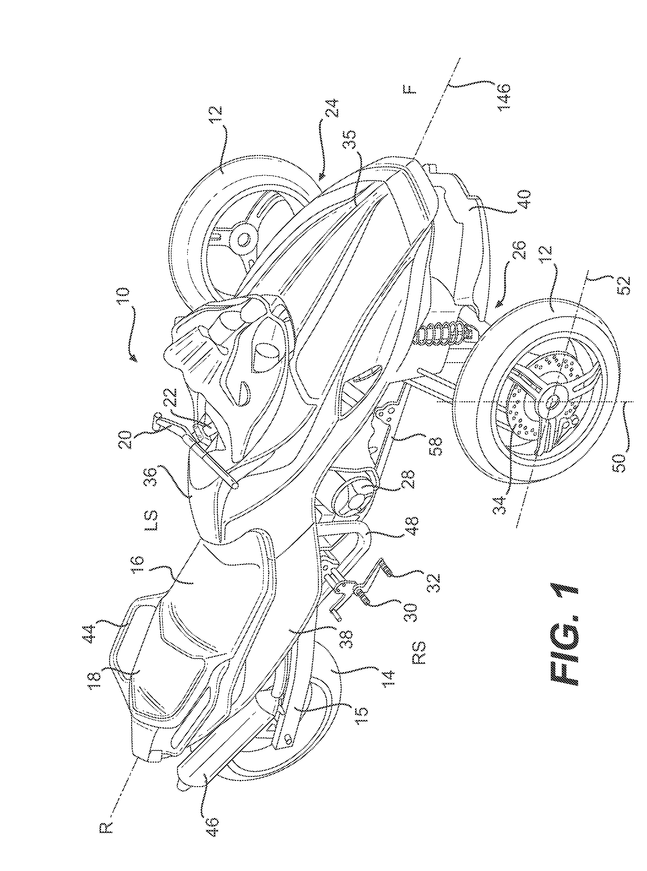
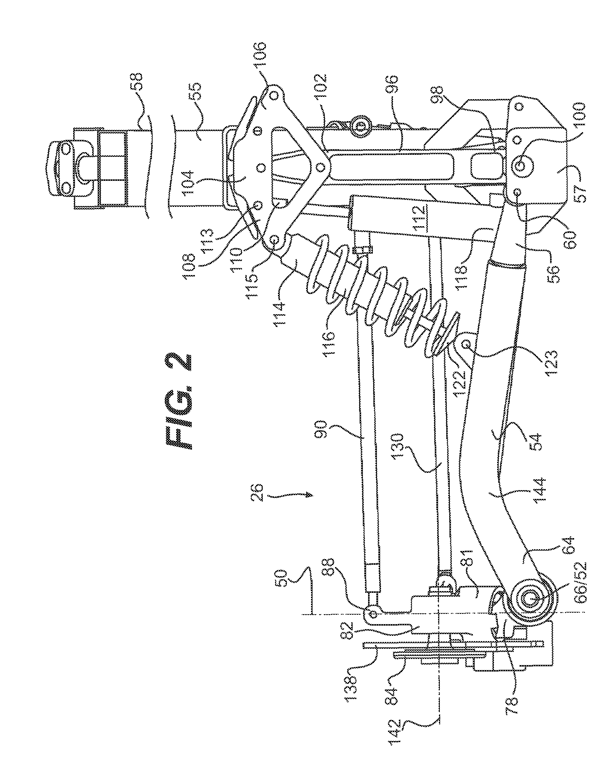
[0058]FIG. 9 is a block diagram illustrating an hydraulic and electronic circuit of an assisted leaning system in accordance with the invention. The sensor 163 measures the torque applied to the steering column 22, sends a signal to the ECU 77 representative of the magnitude and direction of the torque. The ECU 77 also receives signals from the speed sensor 149. In response to the signal from sensor 163, the ECU 77 sends a signal to a four-way valve 129 proportional to the signal received from sensor 163 and correlated to the signal of the speed sensor 149 which directs the fluid pressure generated by the hydraulic pump P to extend or retract the hydraulic actuators 112R and 112L. The ECU 77 also preferably receives signals from a lean angle sensor 147 representative of the relative angle between the shock tower 96 and the frame 58 to keep track of the angle of the frame 58 relative to the shock tower 96.

second embodiment

[0059]FIG. 10 illustrates an assisted leaning system in accordance with the invention. A gearbox 180 is fixedly mounted to the lower member 59 of the frame 58. With reference to FIGS. 10 and 11, the gearbox 180 includes an electric motor 182 having a rotating gear engaging a gear 184 which is fixed to the bottom portion 98 of the shock tower 96 and co-axial with the leaning axis 100. When the electric motor 182 is activated, the electric motor 182 rotates around the fixed gear 184 and force the gearbox 180 and the frame 58 to rotate about the leaning axis 100. The vehicle 10 leans to one side or the other depending on the direction of rotation of the electric motor 182. An ECU 192 is electrically connected to the electric motor 182 of the gearbox 180 and controls the speed and direction of rotation of the electric motor 182.

[0060]It is also contemplated that the electric motor 182 be mounted to the shock tower 96 and the fixed gear 184 be mounted to the frame 58 such that when the e...


PUM


Abstract

A leaning vehicle has a frame pivotally connected to the lower end of a shock tower, the pivotal connection defining a frame leaning axis wherein the frame is adapted to lean to a right side and to a left side relative to the shock tower about the frame leaning axis. The leaning vehicle includes an actuator operatively connected to the frame and to the shock tower which is adapted to impart a leaning motion to the frame relative to the shock tower about the frame leaning axis.

Description

CROSS REFERENCES TO RELATED APPLICATIONS[0001]The present Utility Patent Application claims priority from U.S. Provisional Patent Application No. 60 / 696,532 filed Jul. 6, 2005; the contents of which are incorporated herein by reference.FIELD OF THE INVENTION[0002]The present invention relates to front suspension assemblies in general and in particular relates to a front suspension for a vehicle adapted to lean into a turn.BACKGROUND OF THE INVENTION[0003]Leaning vehicles having more than one front or rear wheels require a frame that is pivotally connected to the two-wheel suspension assembly to permit the vehicle to lean. One such vehicle is disclosed in U.S. Pat. No. 6,328,125 (Van Den Brink et al.), which describes a three-wheel vehicle having a frame pivotally connected to a two-wheel rear suspension assembly, and drive train structured in such a way that, the frame and the front wheel can lean into a corner while the two rear wheels remain substantially vertical.[0004]In additio...

Claims


Application Information

Patent Timeline
IPC IPC(8): B60G21/00B60G7/00B62D61/06
CPCB60G21/007B62K5/027B62K5/05B62K5/08B62K5/10B60G2200/14B60G2202/413B60G2202/42B60G2204/46B60G2300/122B60G2300/45B60G2400/0511B60G2400/204B60G2400/252
Inventor MERCIER, DANIEL
Owner BOMBARDIER RECREATIONAL PROD INC
Why Eureka
Try Eureka