A/D converter and A/D conversion method

a converter and converter circuit technology, applied in the direction of code conversion, transmission system, instruments, etc., can solve the problem that the power consumed by these a/d converter circuits occupies a large proportion of the entire power consumption

Inactive Publication Date: 2010-01-19
SOCIONEXT INC
View PDF5 Cites 2 Cited by
  • Summary
  • Abstract
  • Description
  • Claims
  • Application Information

AI Technical Summary

Benefits of technology

[0030]As described above, in the A / D converter and the A / D conversion method of the present invention, convergence to a target value of operational amplification in the operational amplification operation by the A / D converter circuit can be sped up. Therefore, a high-speed, low-power A / D converter can be implemented.BRIEF DESCRIPTION OF THE INVENTION
[0031]FIG. 1 is a block diagram of an A / D converter of Embodiment 1 of the present invention.
[0032]FIG. 2 is an operation timing chart of the A / D converter.
[0033]FIG. 3 is a circuit diagram showing an internal configuration of an initial value setting circuit in the A / D converter.
[0034]FIG. 4 is a block diagram of an A / D converter of Embodiment 2 of the present invention.
[0035]FIG. 5 is an operation timing chart of an A / D converter of Embodiment 3.

Problems solved by technology

The power consumed by these A / D converter circuits occupies a large proportion of the entire power consumption.

Method used


Image

  • A/D converter and A/D conversion method
  • A/D converter and A/D conversion method
  • A/D converter and A/D conversion method

Examples


embodiment 1

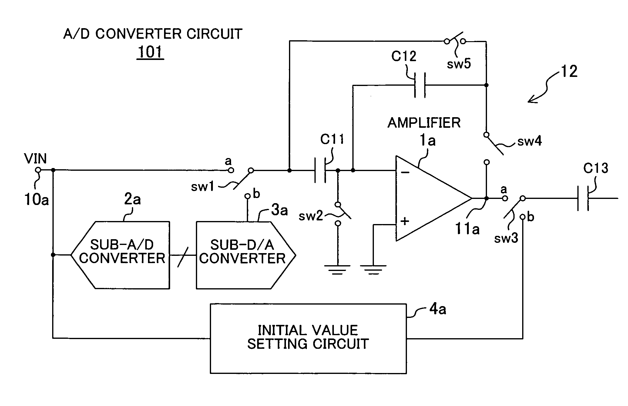
[0054]FIG. 1 is a block diagram of an A / D converter of Embodiment 1 of the present invention.

[0055]In an A / D converter circuit 101 shown in FIG. 1, the reference numeral 1a denotes an amplifier used in operational amplification of an input signal VIN received via an input terminal 10a, which outputs an operationally-amplified digital signal from an output terminal 11a. The reference numeral 2a denotes a sub-A / D converter for A / D-converting the input signal VIN received via the input terminal 10a, and 3a denotes a sub-D / A converter for D / A-converting a digital input signal A / D-converted by the sub-A / D converter 2a to determine a reference voltage used for addition / subtraction in the next amplification period. The reference numerals C11 and C12 denote first and second capacitors, and 12 denotes a switch group composed of five switches SW1, SW2, SW3, SW4 and SW5. The switch group 12 is for switching the connections among the first and second capacitors C11 and C12, the input terminal 1...

embodiment 2

[0073]Next, an A / D converter of Embodiment 2 will be described.

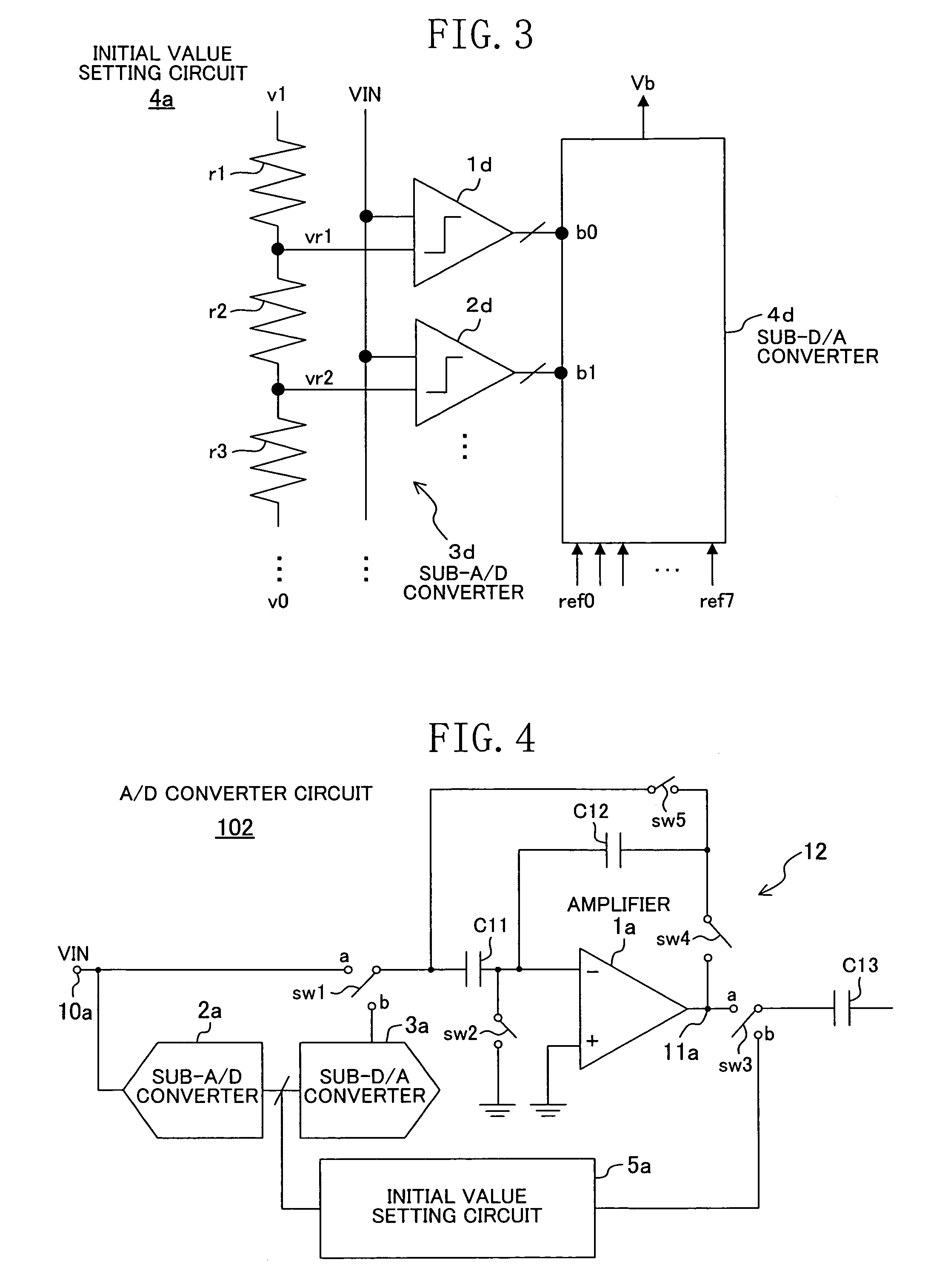
[0074]In Embodiment 1, the initial value setting circuit 4a includes the sub-A / D converter 3d as shown in FIG. 3. In this embodiment, the sub-A / D converter 2a of the A / D converter circuit also serves as a substitute for the sub-A / D converter 3d.

[0075]FIG. 4 is a block diagram of the A / D converter of Embodiment 2 of the present invention.

[0076]In an A / D converter circuit 102 shown in FIG. 4, the reference numeral 5a denotes an initial value setting circuit for setting the initial value of the output voltage in the operational amplification by the A / D converter circuit 102. The initial value setting circuit 5a receives digital input signals from the sub-A / D converter 2a that A / D-converts the analog input signal VIN to decide the voltage level of the analog input signal VIN. Therefore, the initial value setting circuit 5a, which is different from the initial value setting circuit 4a shown in FIG. 3 in that the sub-A / D conv...

embodiment 3

[0079]An A / D converter of Embodiment 3 of the present invention will be described.

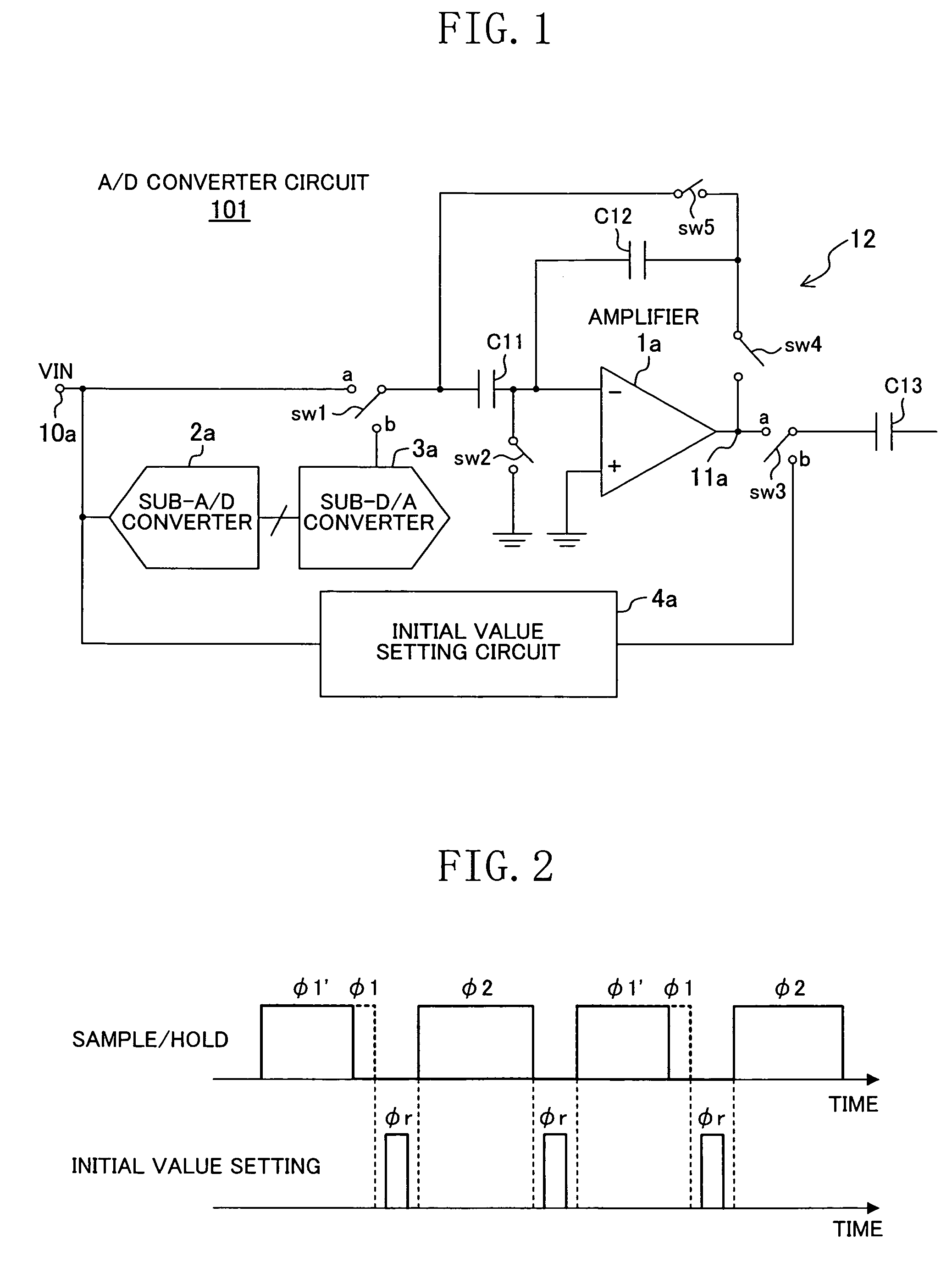
[0080]In Embodiment 1, the initial value setting period φr was provided between the sampling periods φ1 and φ1′ and the amplification period φ2. In this embodiment, the initial value setting period φr is set to start at the time point of termination of the decision of the voltage level in the sub-A / D converter 3d or 2a.

[0081]In this embodiment, the circuit configurations in Embodiments 1 and 2 can be used. Hereinafter, the operation will be described using the circuit configuration in Embodiment 2.

[0082]In the timing chart of FIG. 5, φ1 and φ1′ denote sampling periods and φ2 denotes an amplification period. Time t1 represents the time at which A / D conversion by the sub-A / D converter 2a is terminated. The target value of operational amplification by the A / D converter circuit 102 must have been finalized at this time, and thus at and after this time, shifting to the initial value setting period φr is po...


PUM


Abstract

In an A / D converter provided with an A / D converter circuit 101 for operationally amplifying an input signal and outputting an amplified signal, the A / D converter circuit 101 includes an initial value setting circuit 4a in addition to an amplifier 1a, a sub-A / D converter 2a, a sub-D / A converter 3a and capacitors C11 and C12. To ensure that the initial value of the output voltage of the amplifier 1a is a given voltage value close to the target value of operational amplification at the start of the operational amplification by the amplifier 1a, the initial value setting circuit 4a applies a given bias value equal to the given voltage value close to the target value to a next-stage capacitor C13 to be connected to the output side of the amplifier 1a. Such an A / D converter circuit 101 that can perform speedy convergence to the target value of operational amplification is used at each stage of a pipeline A / D converter.

Description

RELATED APPLICATIONS[0001]This application is the U.S. National Phase under 35 U.S.C. §371 of International Application No. PCT / JP2006 / 305935, filed on Mar. 24, 2006, which in turn claims the benefit of Japanese Application No. 2005-270172, filed on Sep. 16, 2005, the disclosures of which Applications are incorporated by reference herein.FIELD OF THE INVENTION[0002]The present invention relates to an A / D converter and an A / D conversion method.BACKGROUND ART[0003]A pipeline type A / D converter includes a plurality of A / D converter circuits, and each of the A / D converter circuits bears a very important function. The power consumed by these A / D converter circuits occupies a large proportion of the entire power consumption. Such A / D converter circuits constituting a pipeline A / D converter are required to perform operational amplification operation including multiplication and addition / subtraction for an input signal.[0004]As an exemplary configuration, such an A / D converter circuit inclu...

Claims


Application Information

Patent Timeline
Patent Type & Authority Patents(United States)
IPC IPC(8): H03M1/38
CPCH03M1/168
Inventor OZEKI, TOSHIAKINOMASAKI, DAISUKEOKA, KOJI
Owner SOCIONEXT INC
Why Eureka
Try Eureka