
Digital phase locked loop with reduced convergence time

a digital phase and convergence time technology, applied in the field of phase locked loops, can solve problems such as unacceptably long time, and achieve the effects of reducing the convergence time, speeding up the remaining phase convergence of the dpll, and low loop bandwidth

Active Publication Date: 2015-01-27
MICROSEMI SEMICON
View PDF15 Cites 10 Cited by
  • Summary
  • Abstract
  • Description
  • Claims
  • Application Information

AI Technical Summary

Benefits of technology

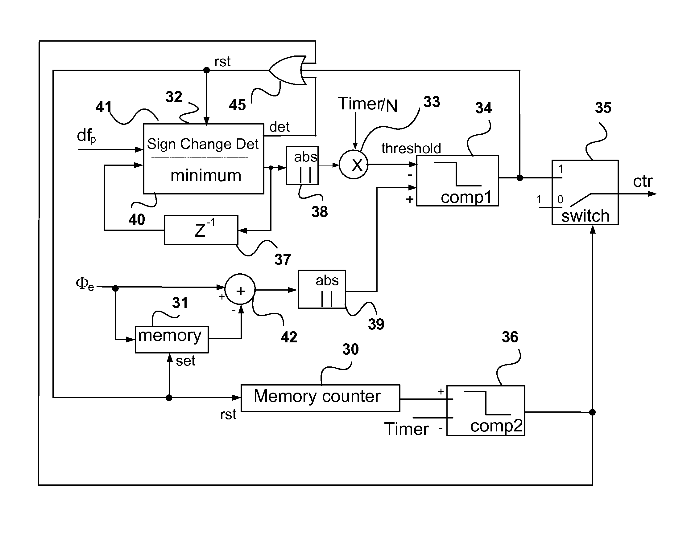
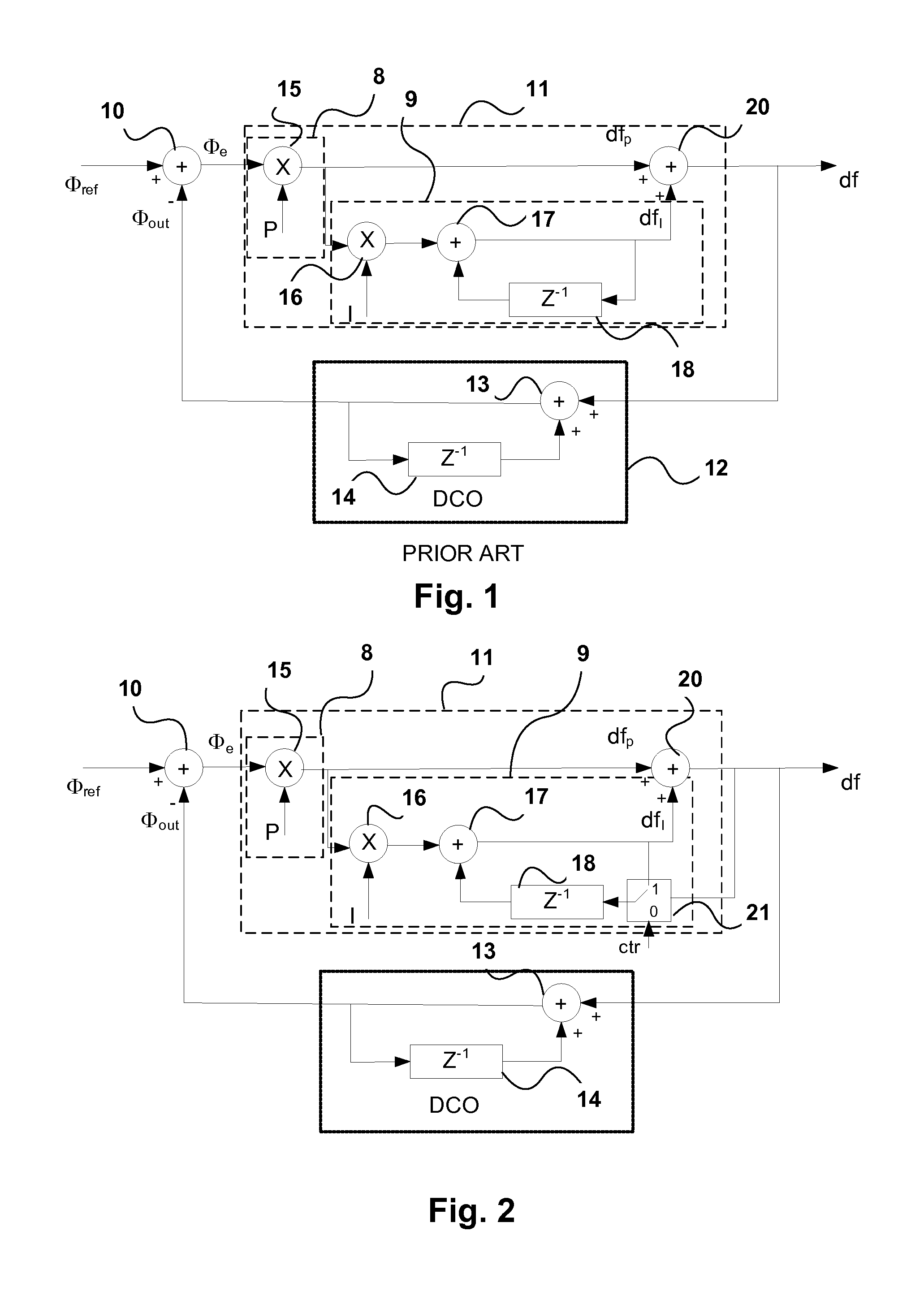
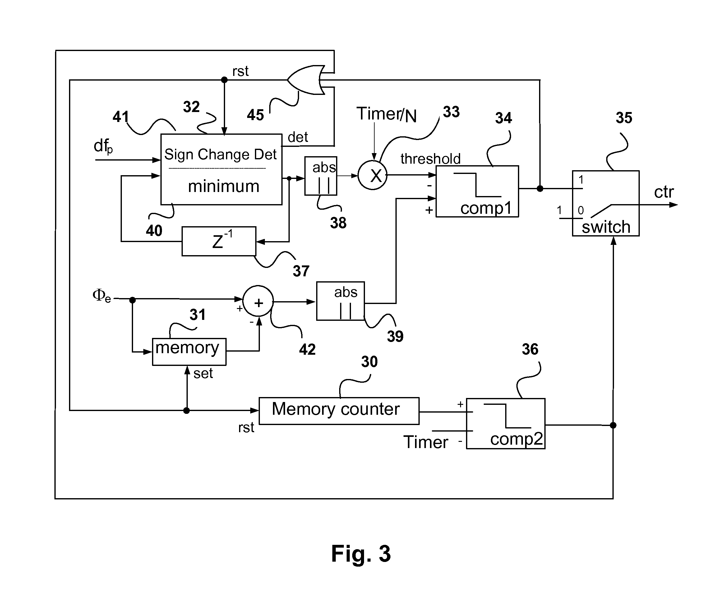
[0015]Embodiments of the invention are based on the fact that if the frequency has converged (is in lock), the integral component dfI at the output of the integral part should be 0 ppm (parts per million) compared with the frequency of the reference clock. Under these circumstances the phase component dfp should normally eliminate any residual phase error within a given time period.
[0018]With this arrangement it is possible to speed up the remaining phase convergence of a DPLL with very low loop bandwidth.
[0019]According to another aspect of the invention there is provided a method of reducing the convergence time in a digital phase locked loop, comprising comparing the phase of an output signal having phase and frequency, or a signal derived therefrom, with a reference signal to produce a phase error signal; filtering said phase error signal in a loop filter having a proportional part producing a proportional component and a integral part producing an integral component, said integral part including a delayed feedback loop normally receiving at an input thereof said integral component; applying the proportional and integral components to respective first and second inputs of an adder to produce a control signal; and replacing the integral component at the input of the delayed feedback loop with the produced control signal for brief periods when the phase error signal is non-zero and the rate of change of phase is less than a threshold value.

Problems solved by technology

As the integrator accumulates phase error, the frequency difference df will gradually change to correct the phase error, but this will take an unacceptably long time due to the integration involved and loop bandwidth.

Method used


Image

  • Digital phase locked loop with reduced convergence time
  • Digital phase locked loop with reduced convergence time
  • Digital phase locked loop with reduced convergence time

Examples


Embodiment Construction

[0024]In a traditional DPLL architecture as shown in FIG. 1, the filter response H(z) is given by the expression:

[0025]H⁡(z)=P+I-PZ-11+P+I-(2⁢+P)⁢Z-1+Z-2

where P and I are the scaling factors for the proportional and integral parts respectively. When I<

[0026]H⁡(z)=P1+P-Z-1

[0027]The DPLL bandwidth is determined by the pole, which is only related to the value of the scaling factor P. However, the DPLL behavior changes when the control signal df=(dfp+dfI) equals or is close to zero ppm (parts per million), but Φe is a non-zero value. In this case, if df=0, and therefore dfp+dfI=0. If Φe is non-zero, dfI must have a small frequency offset dfI=−dfp=−P*Φe so that the sum dfp+dfI=df=0. It will be appreciated that the reference frequency itself can have a small offset relative to its nominal value. In this case when the output frequency is locked relative to the actual reference frequency, i.e. has zero ppm offset relative to the actual ...


PUM


Abstract

A digital phase locked loop has a digital controlled oscillator, a phase comparator comparing the output signal of the digital controlled oscillator, or a signal derived therefrom, with a reference signal to produce a phase error signal. A loop filter produces a control signal for the digital controlled oscillator from an output of the phase comparator the loop filter. The loop filter has a proportional part producing a proportional component of the control signal, an integral part producing an integral component of the control signal, and an adder receiving the respective proportional and integral components at first and second inputs thereof to produce the control signal. The integral part includes a delayed feedback loop normally configured to accept the integral component at an input thereof. A first switch replaces the integral component at the input of the delayed feedback loop by the control signal in response to an activation signal. A control module produces the activation signal to activate the switch for brief periods when the phase error is non-zero and the rate of change of phase is less than a threshold value.

Description

CROSS REFERENCE TO RELATED APPLICATION[0001]This application claims the benefit under 35 USC 119(e) of U.S. provisional application No. 61 / 839,937 filed Jun. 27, 2013.FIELD OF INVENTION[0002]This invention relates to the field of phase locked loops (DPLLs), and in particular to digital phase locked loops with second order loop filters.BACKGROUND OF THE INVENTION[0003]A digital phase locked loop (DPLL) in general comprises a phase comparator, a loop filter, a controlled oscillator, and a feedback path. The feedback signal is compared with a reference signal to generate an error signal. The loop filter filters the error signal to generate the control signal for the digital controlled oscillator. In this way the output of the phase locked loop is locked to the reference signal. The convergence time is the time it takes for the output to lock on to the reference signal and is proportional to the filter bandwidth. A low filter bandwidth is desirable to reduce jitter but this implies a lo...

Claims


Application Information

Patent Timeline
Patent Type & Authority Patents(United States)
IPC IPC(8): H03L7/06H03L7/093H03L7/14
CPCH03L7/093H03L7/145H03L2207/50H03L2207/18H03L7/1075
Inventor JIN, QU GARY
Owner MICROSEMI SEMICON
Learn More