
Flex circuit dampener for reduction of seek induced vibrations in a disk drive

a flex circuit and disk drive technology, applied in the direction of instruments, record information storage, support for heads, etc., can solve the problems of most vibrational loading on the actuator assembly, and achieve the effect of dampening vibrational loads, reducing errors, and reducing vibrations

Inactive Publication Date: 2010-01-19
SEAGATE TECH LLC
View PDF8 Cites 13 Cited by
  • Summary
  • Abstract
  • Description
  • Claims
  • Application Information

AI Technical Summary

Benefits of technology

[0010]Thus, it is a long felt need in the field of magnetic disk drive construction to provide a device and method that reduces errors from post seek oscillations of the transducer head by dampening the vibrational loads generated by the flex circuit. The following disclosure describes a dampening mechanism that interfaces with the flex circuit of a disk drive actuator arm to reduce the vibrations emanating therefrom. More specifically, the flex circuit of many disk drives is interconnected to a flex clamp that is situated on or near an electrical connector that interconnects the flex circuit with the printed circuit board of the disk drive that, in turn, is interconnected with a computer system. The flex clamp is generally a molded plastic member that secures a portion of the flex circuit to the electrical connector. The flex circuit extends from the flex clamp and travels in a curved or arcuate path to the actuator, thereby providing slack and accommodating free movement of the actuator.
[0011]One embodiment of the present invention is a spring-like mechanism that interconnects with the clamp to engage one portion of the flex circuit, thus providing dampening to help lower the first resonant mode or natural frequency of the flex circuit. In one embodiment of the present invention, the flex circuit dampener is inserted between the flex circuit and a wall of the flex clamp to provide a spring similar to that of a leaf spring. More specifically, this embodiment of the present invention provides a flexible surface that engages the flex circuit to provide localized dampening by deflectional and frictional loading of the surface of the flex circuit, thus removing vibrational energy from the flex circuit.
[0012]One skilled in the art will appreciate that many types of dampeners may be employed without departing from the scope of the invention, such that many shapes or sizes of various types of materials may be employed. The aim of all of the embodiments of this invention is to provide a dampener placed in contact with the flexing portion of the flex circuit, which is typically but not necessarily located between the actuator assembly and the flex clamp. In operation, a dampener of a specific range of stiffness and dampening values may effectively modify the mechanical response of a flex circuit during a seek operation and reduce the reaction of forces or torques exerted on the actuator by the flex circuit that results in post seek oscillations that, in turn, reduce seek time performance. Both the dimensional and material properties of the dampener are important for achieving the correct stiffness and dampening properties of the dampener. Similarly, the dimensional and material properties of the flex circuit are also relevant for achieving the correct stiffness and dampening properties of the dampener. The flex circuit dampener may be a rectangular piece of material that is interconnected to the wall of the flex clamp, thus making the present invention easy to retrofit into existing designs of disk drives. In one embodiment of the present invention, the flex dampener is a rectangular piece of Kapton 75 microns thick and about 35 millimeters in height that is positioned between the flex clamp and the flex circuit.

Problems solved by technology

In addition, the flex circuit dampener reduces the magnitude of the resonant frequencies, especially the first mode frequency, which is the most prominent and which causes the most vibrational loading on the actuator assembly.

Method used


Image

  • Flex circuit dampener for reduction of seek induced vibrations in a disk drive
  • Flex circuit dampener for reduction of seek induced vibrations in a disk drive
  • Flex circuit dampener for reduction of seek induced vibrations in a disk drive

Examples


Embodiment Construction

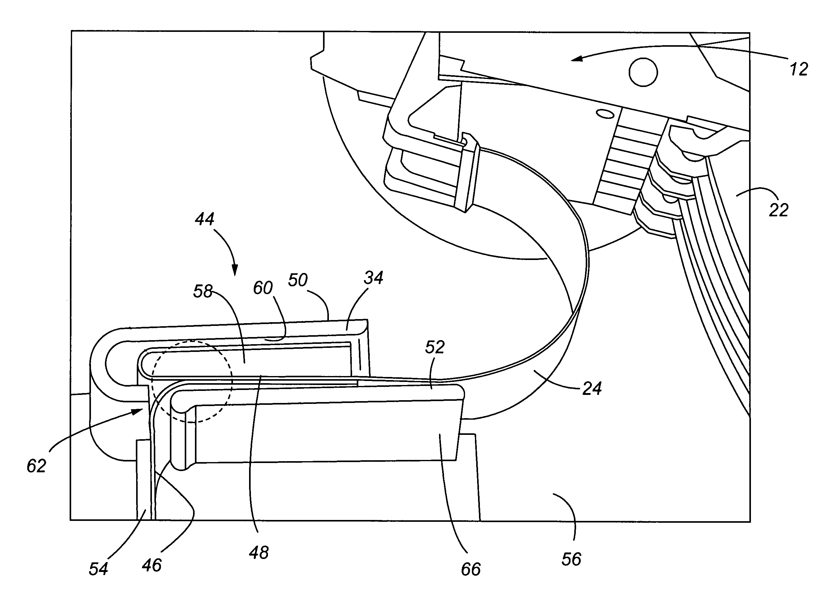
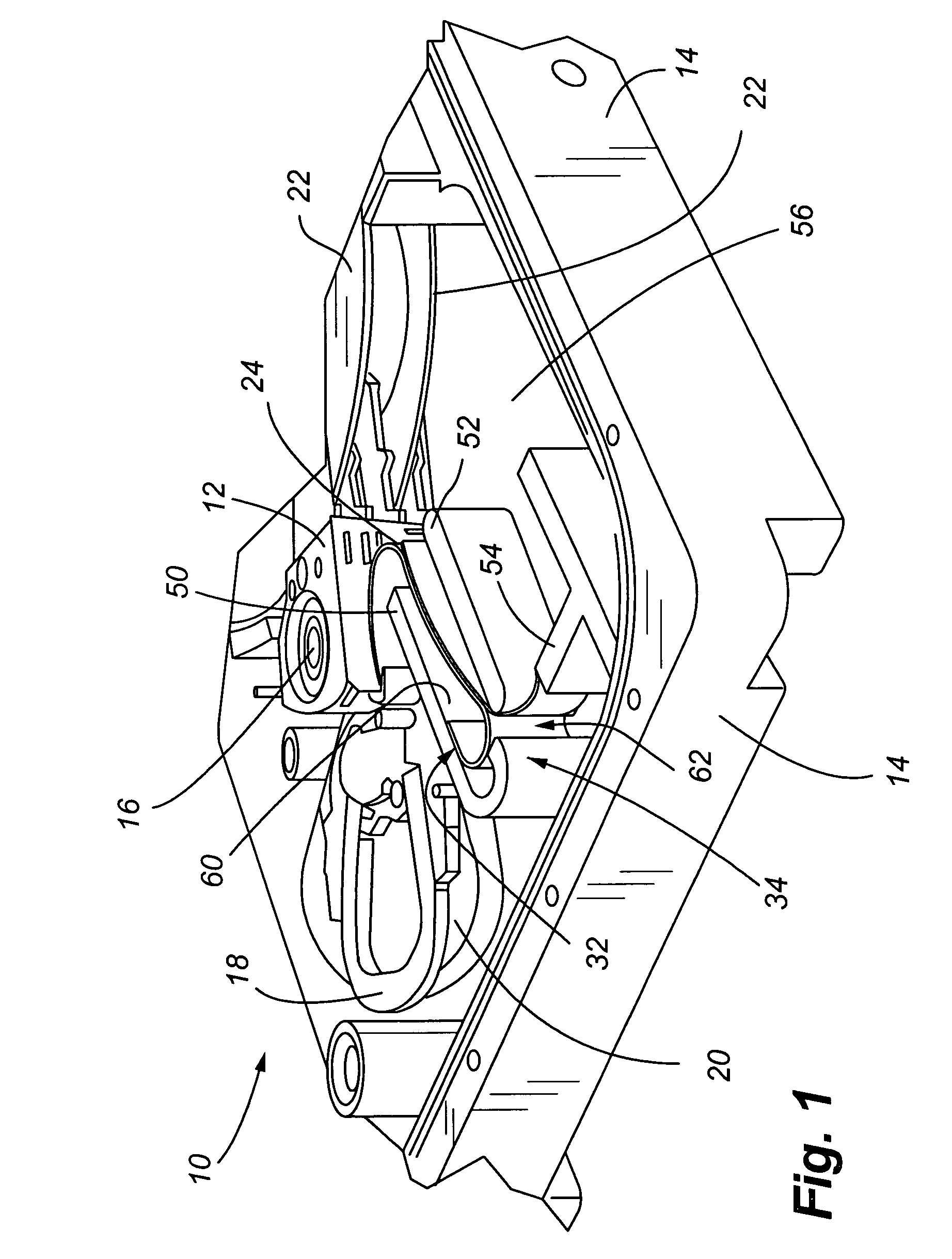
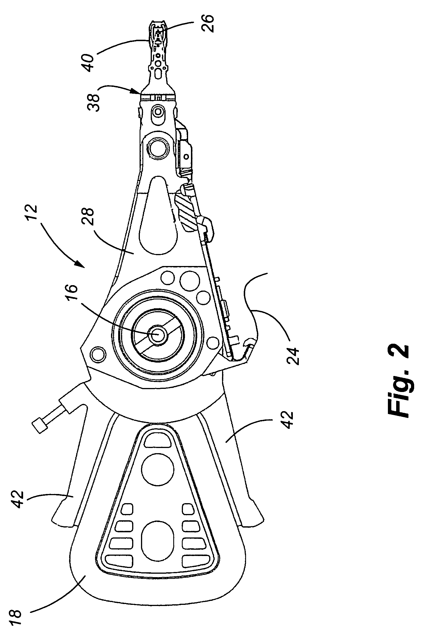
[0033]Referring now to FIGS. 1-6, a disk drive and flex circuit dampening device is shown. More specifically, in FIG. 1, a partial view of a disk drive 10 is shown. An actuator assembly 12 is connected to a base plate 14 and rotates about a pivot 16. A voice coil 18, in combination with a pair of permanent magnets 20, only one of which is shown, causes rotary movement of the actuator assembly 12 relative to spinning disk 22. A flex circuit 24 supplies energy to the voice coil. The flex circuit 24 is also the primary path for transmitting data between a transducer or head 26, positioned at the distal end of each actuator arm 28 (FIG. 2), and a printed circuit board typically mounted on the opposite side of the base plate 14 as shown in FIG. 1 (not shown). The flex circuit 24 contains a plurality of electrical traces (not shown) that interconnect the transducer and voice coil to the various processors and other components on the printed circuit board. The electrical traces interface w...


PUM

PropertyMeasurementUnit
ninety degree angleaaaaaaaaaa
thickaaaaaaaaaa
thickaaaaaaaaaa

Abstract

The present invention is a dampening device for a flex circuit of a disk drive. The dampening device engages the flex circuit to alter is vibrational effect generated by the moment of the flex circuit that adversely affects post seek oscillations performance of the drive. The dampening device lowers the first resonant frequency of the flex circuit and reduces the magnitude of the post seek off track oscillations.

Description

CROSS-REFERENCE TO RELATED APPLICATIONS[0001]This application claims the benefit of U.S. Provisional Patent Application Ser. No. 60 / 560,831, filed Apr. 8, 2004, which is incorporated by reference in its entirety herein.FIELD OF THE INVENTION[0002]The present invention relates to the reduction of vibrational loads imparted upon an actuator in a disk drive as a result of a seek operation. In particular, one embodiment of the invention dampens vibrational inputs originating from a flex circuit interconnected to the actuator to reduce post seek oscillation levels resulting in improved seek performance.BACKGROUND OF THE INVENTION[0003]Hard disk drives store information on magnetic disks. Typically, the information is stored on concentric tracks of the disk that are divided into servo sectors and data sectors. Information is written to or read from the disk by a transducer or head, mounted on an actuator arm that positions the transducer over the disk in a predetermined location. Accordin...

Claims


Application Information

Patent Timeline
Patent Type & Authority Patents(United States)
IPC IPC(8): G11B5/54
CPCG11B5/4846
Inventor EDWARDS, JOHN ROBERT
Owner SEAGATE TECH LLC
Learn More