Method of assembling conductive terminals of a plurality of electrical connectors and electrical connector module assembled thereby

a technology of electrical connectors and conductive terminals, which is applied in the direction of coupling device details, line/current collector details, coupling device connections, etc., can solve the problems of reducing increasing manufacturing costs, and wasting a lot of materials, so as to improve assembly quality and production efficiency. , the effect of greatly improving the utilization rate of terminal carrier structures

Active Publication Date: 2010-01-26
LOTES
View PDF1 Cites 12 Cited by
  • Summary
  • Abstract
  • Description
  • Claims
  • Application Information

AI Technical Summary

Benefits of technology

[0009]An object of the present invention is to provide a method of assembling conductive terminals of a plurality of electrical connectors which is convenient for assembly of conductive terminals and has low manufacturing cost and high production efficiency.
[0011]In the method of assembling conductive terminals of a plurality of electrical connectors of the present invention, the terminal carrier structure has the carrier and at least two conductive terminal groups are alternately disposed on the carrier, so the material utilization rate of the terminal carrier is improved greatly, unnecessary waste is reduced and the manufacturing cost is reduced. Each guiding hole is partially overlapping one of the fixing holes and the free end of each conductive terminal is inserted into the corresponding fixing hole along the corresponding guiding hole; that is, the guiding holes have the function of guiding the conductive terminals, so that the conductive terminals can be correctly correspondingly inserted in the corresponding fixing holes during assembly, even if the free ends of the conductive terminals cannot completely correspond to the corresponding fixing holes originally. Furthermore, the terminal carrier structure has the carrier and at least two conductive terminal groups are alternately disposed on the carrier, wherein each conductive terminal group has at least two conductive terminals each of which has a free end extending from, and there is height difference between the position of each free end of one of the conductive terminal groups and the position of each free end of the other conductive terminal group, and each free end of each conductive terminal group corresponds to one of the guiding holes of one of the terminal receiving portions, respectively. Then the terminal carrier structure is disposed behind the overlapping at least two housings so that the free end of each conductive terminal is located behind one of the guiding holes, respectively. Push the terminal carrier structure so that the free end of each conductive terminal is inserted into the corresponding fixing hole along the corresponding guiding hole; and remove the carrier so that each conductive terminal is separated from the carrier and each housing and the conductive terminal group engaged in the housing form one electrical connector. Accordingly, the assembly procedure is reduced, the production efficiency is improved and the manufacturing cost is reduced.
[0012]Another object of the present invention is to provide an electrical connector module which is assembled by method of assembling conductive terminals of a plurality of electrical connectors. The electrical connector module is convenient for assembly and has low manufacturing cost and high production efficiency.
[0014]In the electrical connector module of the present invention, since each guiding hole has at least one guiding surface connected with one of the fixing holes; that is, each guiding surface has the function of guiding the corresponding conductive terminal, the conductive terminal can be correctly correspondingly inserted in the corresponding fixing hole during assembly, even if the conductive terminal cannot completely correspond to the corresponding fixing hole originally, thereby improving assembly quality and production efficiency effectively. At least two electrical connectors are overlapping up and down and the carrier disconnected portions of the two electrical connectors are cut from the same carrier, so the material utilization rate of the terminal carrier structure is improved greatly, unnecessary waste is reduced and the manufacturing cost is reduced. Furthermore, the carrier disconnected portions of at least two of the electrical connectors are cut from the same carrier, that is, during assembly, at least two conductive terminal groups connected with the same carrier are respectively inserted in at least two terminal receiving portions of the housings, and after the two conductive terminal groups are cut from the same carrier, each housing and the conductive terminal group correspondingly received in the housing can form one electrical connector. Accordingly, the assembly procedure is reduced, the production efficiency is improved and the manufacturing cost is reduced.

Problems solved by technology

Since the center distance (2.0 mm-2.5 mm) between two adjacent conductive terminals of each conductive terminal group is far greater than the width (about 1.0 mm) of each conductive terminal (please refer to FIG. 16 simultaneously), more waste material (the width of about 1.0 mm-1.5 mm) is produced between each two adjacent conductive terminals, which reduces the utilization rate of the terminal carrier structures 901, 902, 903 and 904, brings a great waste of material and increases manufacturing cost.
Additionally, during assembly, one terminal carrier structure 901, 902, 903 or 904 generally corresponds to one assembling step, so two terminal carrier structures need to be assembled in two assembling steps, that is, the conductive terminals of the four conductive terminal groups need to be mounted on an insulating body in four times and then respectively riveted and fixed, thereby the manufacturing and assembling steps are increased, which reduces the assembly efficiency of the conductive terminals and the insulating body and restricts manufacturing cost.

Method used


Image

  • Method of assembling conductive terminals of a plurality of electrical connectors and electrical connector module assembled thereby
  • Method of assembling conductive terminals of a plurality of electrical connectors and electrical connector module assembled thereby
  • Method of assembling conductive terminals of a plurality of electrical connectors and electrical connector module assembled thereby

Examples


Embodiment Construction

[0035]The following is the detailed description of the method of assembling conductive terminals of a plurality of electrical connectors and electrical connector module assembled thereby of the present invention according to the figures.

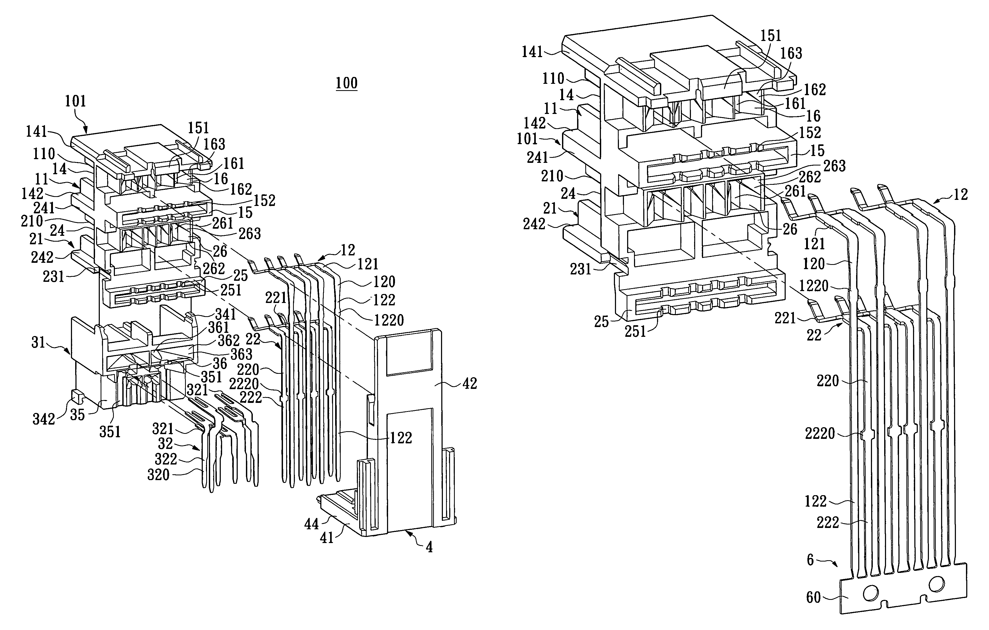
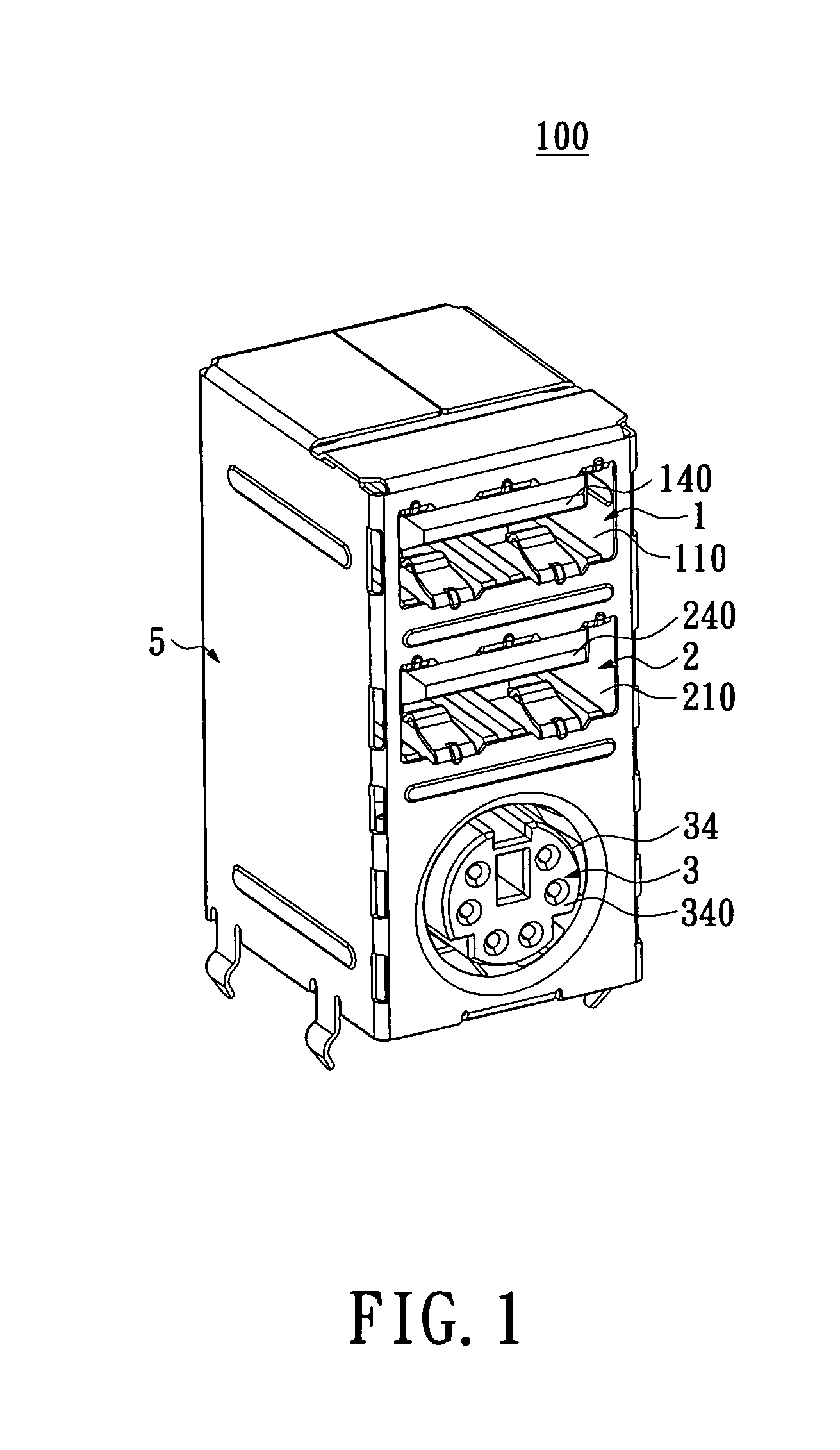
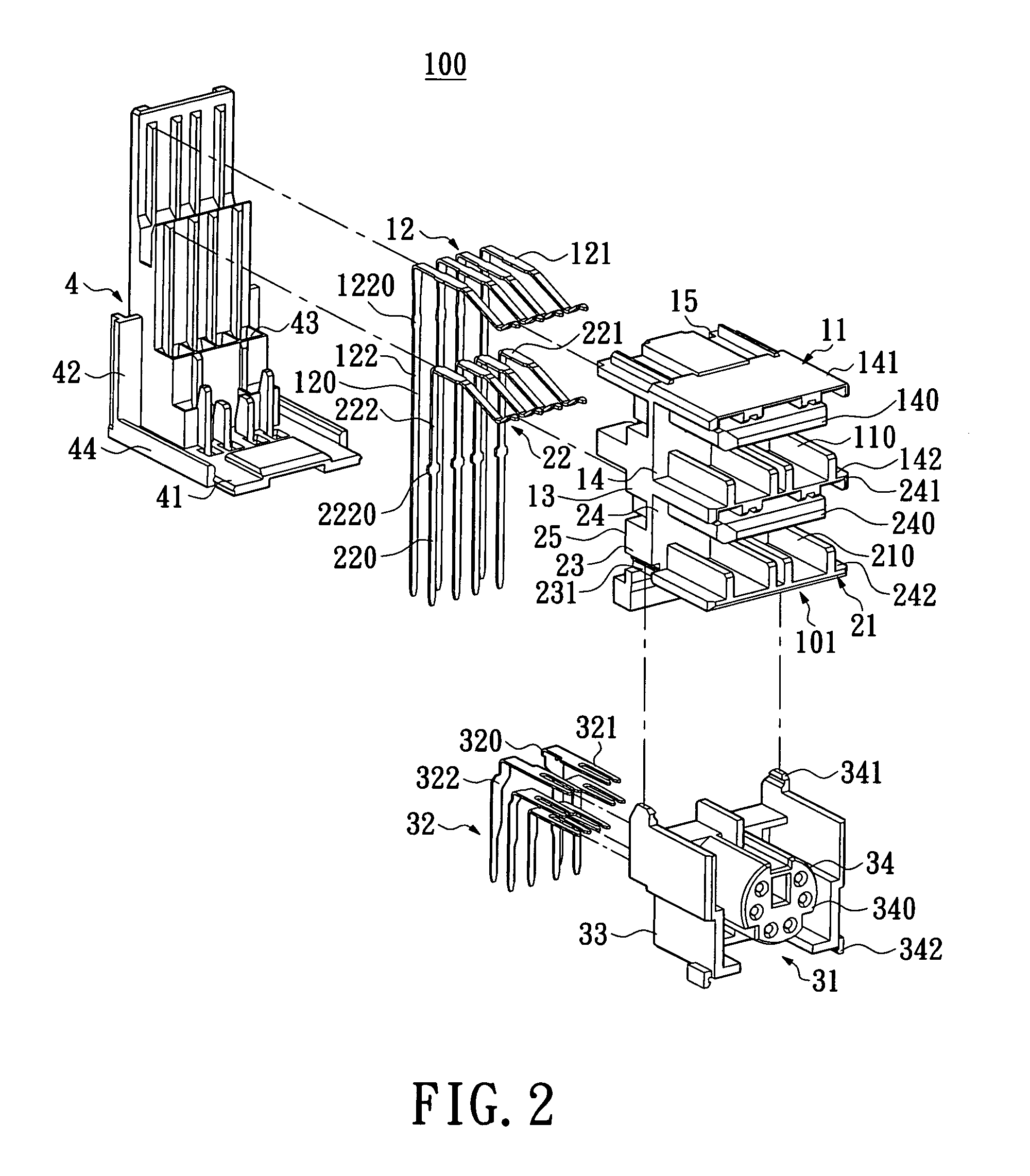
[0036]Please refer to FIGS. 1-3, the electrical connector module 100 of the present invention includes a first electrical connector 1, a second electrical connector 2, a third electrical connector 3 and a shielding shell 5 covering the electrical connector module 100. In the embodiment, the first electrical connector 1, the second electrical connector 2 and the third electrical connector 3 are overlapping up and down, and the first electrical connector 1 and the second electrical connector 2 are USB connectors with the same specification and the same structure and function. Of course, in other embodiments, the first electrical connector 1 and the second electrical connector 2 may also be connectors with the same or similar specification and the same ...


PUM

PropertyMeasurementUnit
widthaaaaaaaaaa
conductiveaaaaaaaaaa
heightaaaaaaaaaa

Abstract

A method of assembling conductive terminals of a plurality of electrical connectors includes the steps of: (1) providing at least two overlapping housings each of which has a terminal receiving portion including fixing holes and guiding holes each partially overlapping one fixing hole; (2) providing a terminal carrier structure with a carrier, wherein at least two conductive terminal groups are alternately disposed on the carrier and each group has at least two conductive terminals with free ends; (3) disposing the carrier structure behind the housings; (4) pushing the carrier structure so that the free ends are inserted into the fixing holes; and (5) removing the carrier so that each conductive terminal is separated from the carrier and each housing and the engaging conductive terminal group form one electrical connector. Accordingly, the present invention can reduce assembly procedure, improve production efficiency and reduce manufacturing cost.

Description

BACKGROUND OF THE INVENTION[0001]1. Field of the Invention[0002]The present invention relates to a method of assembling conductive terminals of a plurality of electrical connectors and electrical connector module assembled thereby.[0003]2. Description of Related Art[0004]With the development of various electronic products and personal computers and the expansion of peripheral equipment for various electronic products, electronic products have more and more connectors. USB (Universal Serial Bus) is an electronic connector for high speed signal transmission. Since USB has the advantages of hot-swap, convenient carry, unified standard and connecting with different kinds of equipment, USB is widely used for connecting various electronic products with peripheral equipment.[0005]At present, an electronic product generally has a plurality of independent USB connectors or a connector module formed by a plurality of USB connectors together disposed therein. As shown in FIG. 19 and FIG. 20, a...

Claims


Application Information

Patent Timeline
Patent Type & Authority Patents(United States)
IPC IPC(8): H01R43/00
CPCH01R43/20H01R12/716Y10T29/49222
Inventor JU, TED
Owner LOTES
Why Eureka
Try Eureka