Belt device

a belt or webbing technology, applied in the direction of driving belts, v-belts, plant protection, etc., can solve the problems of high work intensity and inspection can only take place in the immediate vicinity

Active Publication Date: 2010-01-26
DRAYER FRIEDRICH
View PDF15 Cites 25 Cited by
  • Summary
  • Abstract
  • Description
  • Claims
  • Application Information

AI Technical Summary

Benefits of technology

[0005]Based on these considerations, the objective of the present invention is to provide for a device of the above type, which allows reliable assessment of occurrence of overshooting of a pre-determined tensile force from longer distances.
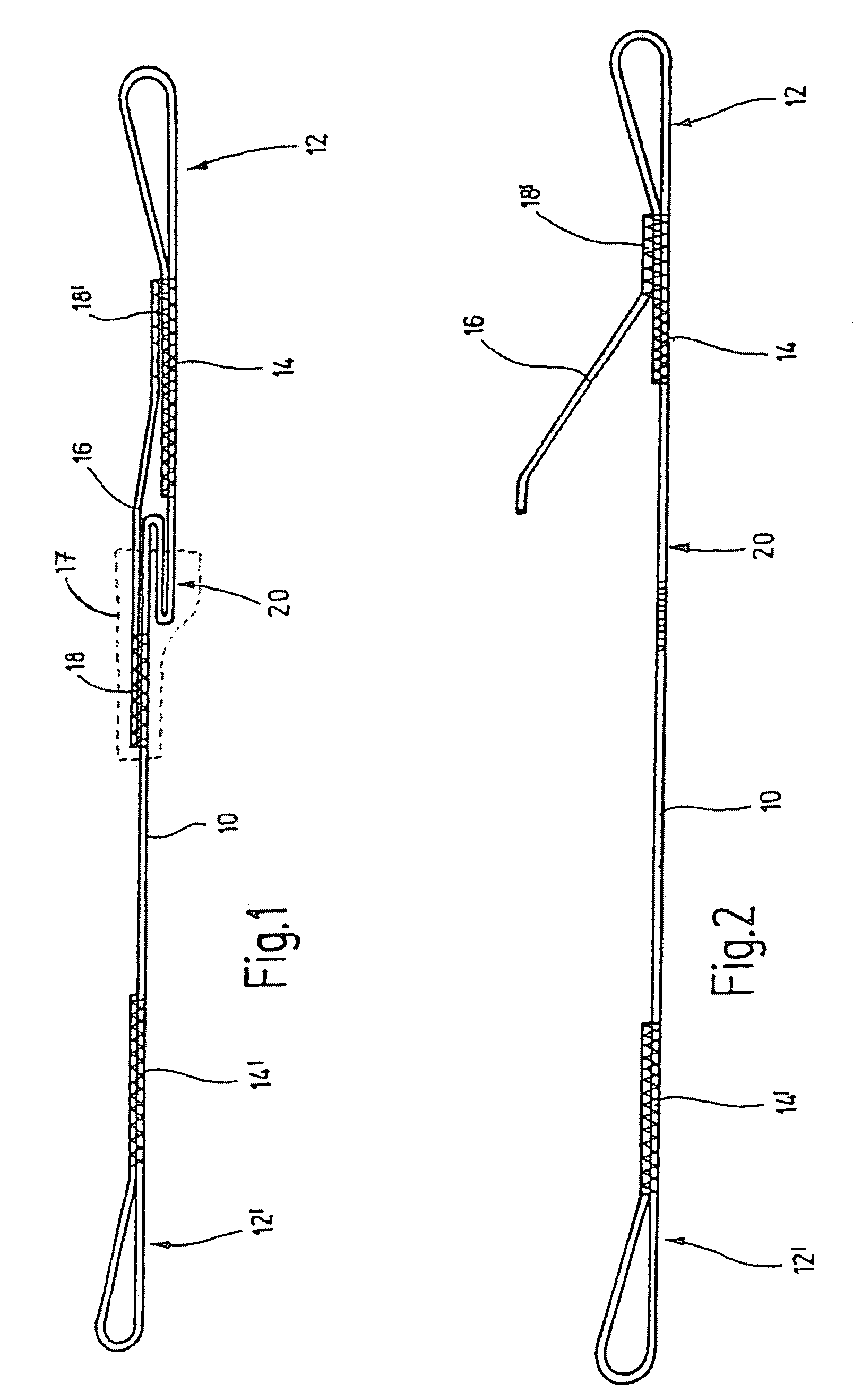
[0007]Based on the concept that an adequately clearly visible indicating element is required for a good visibility from longer distances, it is proposed in the invention that the belt is overlapped by an indicating element in the vicinity of at least one of the loops, which indicating element shortens the belt and is fastened with two end portions on the belt such that one of the fastenings gives way when a pre-determined tensile force acts on the belt, the tensile force being smaller than the minimum tensile force which the loop fastenings and the belt withstand. One of the fastenings of the indicating element thus works as a rated breaking point, where every desired release value can be attained by the design of the fastening, which is preferably achieved by means of a seam.
[0008]In a preferred embodiment of the invention, the belt is enclosed loosely between the loops by a preferably opaque protective tube which also covers particularly the indicating element in the condition where it is fastened at both ends. This protective tube serves as protection against chafing for the clasped part of the tree on one hand. On the other hand, it can be achieved that the indicating element is covered by the protective tube in its not-released condition, while in its released condition; it is clearly visible as it projects out of the corresponding end of the protective tube. To this end, it is of advantage when the fastening of the indicating element which is distant from the loop gives way when the pre-determined tensile force is exceeded.

Problems solved by technology

A drawback here is that an inspection can take place only from the immediate vicinity, as torn identification threads cannot be deciphered with the required certainty from longer distances, like from the ground.
This also entails a high amount of work effort.

Method used


Image

  • Belt device
  • Belt device

Examples


Embodiment Construction

[0018]The belt device, as shown in the drawing, essentially comprises a belt 10, whose ends are turned over to form loops 12, 12′, wherein the end parts of the belt are fastened by seams 14, 14′ on those parts of the belt which are at a distance from the ends. The length of the seam area, the stitching material, as well as the stitching pattern, influence the load bearing capacity of the fastenings. The belt device is intended to be placed around the tree part that is to be secured or supported. Loops 12, 12′ serve to attach a rope or a similar object, which joins together two of the shown belt devices and thus forms a load carrying system in which a weak or damaged tree part is supported by a healthy or stronger part of the tree.

[0019]An indicating element 16 is arranged in the region of the loop 12; this indicating element may also be a piece of belt and is fastened to the belt 10 with its ends. The fastening takes place through seams 18, 18′, wherein the load carrying capacity of...


PUM


Abstract

A belt device for arrangements which are put under tensile load, particularly for systems for the securing of tree crowns, having a belt (10) with a loop at each end (12, 12′) which is formed by turning over the end parts of the belt (10) and fastening the ends to the belt, wherein the fastenings (14, 14′) and the belt (10) are adapted to withstand a pre-determined minimum tensile force. In order to guarantee a good visibility of the indicating element even from greater distances, it is proposed by the invention that the belt (10) is overlapped by an indicating element (16) in the vicinity of at least one of the loops (12), which indicating element shortens the belt (10) and is fastened with two end portions on the belt (10) such that one of the fastenings (18) gives way when a pre-determined tensile force acts on the belt (10), the tensile force being smaller than the minimum tensile force which the loop fastenings (14, 14′) and the belt withstand.

Description

BACKGROUND OF THE INVENTION[0001]1. Field of the Invention[0002]The invention relates especially to a belt or webbing device for arrangements which are under tensile strain, particularly for security systems of tree crowns, and, in general, to a tension device with overload indication.[0003]2. Description of the Related Art[0004]Crown security for trees should guard against breaking away or falling off of parts of the crown, thereby producing safety in the vicinity of the tree. Considering the general interest in preserving a continued existence of the available tree population, it has to be weighed in individual cases whether this safety can be achieved through removal of parts of the tree or adopting crown security measures; the latter is preferred. For security, amongst others, belt devices are used which, for example, comprise separate belts and safety loops. The loops are placed around those parts of the tree, which are to be secured and are joined with one another by ropes. Si...

Claims


Application Information

Patent Timeline
Patent Type & Authority Patents(United States)
IPC IPC(8): A01G9/12A01G17/08A01G17/12
CPCA01G17/10D07B1/145D07B1/148D07B1/18
Inventor DRAYER, FRIEDRICH
Owner DRAYER FRIEDRICH
Why Eureka
Try Eureka