Track assembly for supporting fabrics

a technology of supporting fabrics and tracks, applied in draperies, doors/windows, ceilings, etc., can solve the problems of difficult closing and locking difficult closing of the upper track member, and difficulty in ensuring the fabric is placed. , to achieve the effect of preventing shadowing effects and facilitating fabric placemen

Inactive Publication Date: 2010-01-26
MORRIS MILTON A
View PDF15 Cites 7 Cited by
  • Summary
  • Abstract
  • Description
  • Claims
  • Application Information

AI Technical Summary

Benefits of technology

[0015]In a particularly preferred embodiment, a tab extends upwardly from an upper plate of the upper track adjacent to the second half of the snapping clamp. This prevents shadowing effects which might otherwise would occur if the fabric rests on the upper track directly.
[0017]In another embodiment, or in addition to the previously described embodiment, the base track includes a tension force dissipater. The dissipater typically extends from the first half of the hinge and is comprised of elevated segments of a base plate of the base track. The elevated segments typically form a generally inverted V-shape. The high tension forces applied to the upper track are at least partially transmitted, such as through the strut, to the tension force dissipater and to the surface of the wall or the like. The transmission and dissipation of the tension forces prevents the snapping clamp from becoming disengaged and the fabric being released.

Problems solved by technology

As the fabric sections can be fairly large, this tensioning puts a tremendous strain on the track framework.
A primary shortcoming is that, due to the large tension forces on the upper and lower track members from the fabric, the closing and locking of the upper track member, to which the fabric is attached to the base track member, is very difficult.
Due to the soft and spongy nature of the material, edges tend to be soft and subject to irregularities due to dents caused by handling of the panels.
When wrapped and installed adjacent to other panels, edges tend to be inconsistent with one another and unsightly gaps often result.
However, these gains are not necessarily beneficial toward achieving a desired and specified acoustical target.
Serious differences may exist, however, between acoustical ratings as represented by manufacturers and what actually is delivered by a contractor who has finished the panel to achieve a straight permanent edge.
Adhesive can act as a barrier to the transmission of sound and reduce the panel's acoustical effectiveness.
Other concerns with currently existing fiberglass panels is that they are fixed dimension panels which do not allow for covering out of square walls.
Furthermore, should the consumer wish to change the decor, all of the acoustical material must be replaced at a great expense.
Unfortunately, the track assemblies of the '642 and '364 patents relate to products which are only half-inch systems.
From both a geometric as well as a material standpoint, these designs are impractical for adaption to the dimensions of a one inch fiberglass panel system.
There is also the concern that the top bracket will actually become disengaged with bottom bracket due to the tension forces applied to the track assembly by the tensioned fabric.
Due to the high tension forces, the fabric can slip from the snapping clamp or disengage the snapping clamp.
The hinges of these devices are also prone to failure.
These problems are particularly acute in one-inch systems.

Method used


Image

  • Track assembly for supporting fabrics
  • Track assembly for supporting fabrics
  • Track assembly for supporting fabrics

Examples


Embodiment Construction

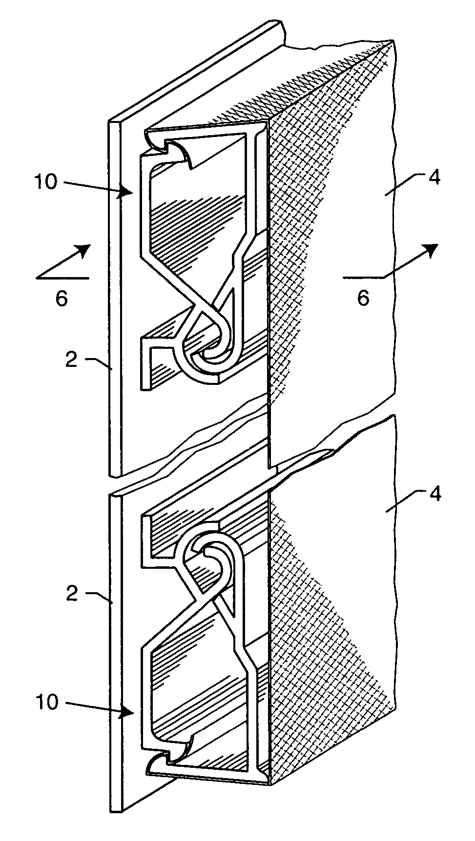
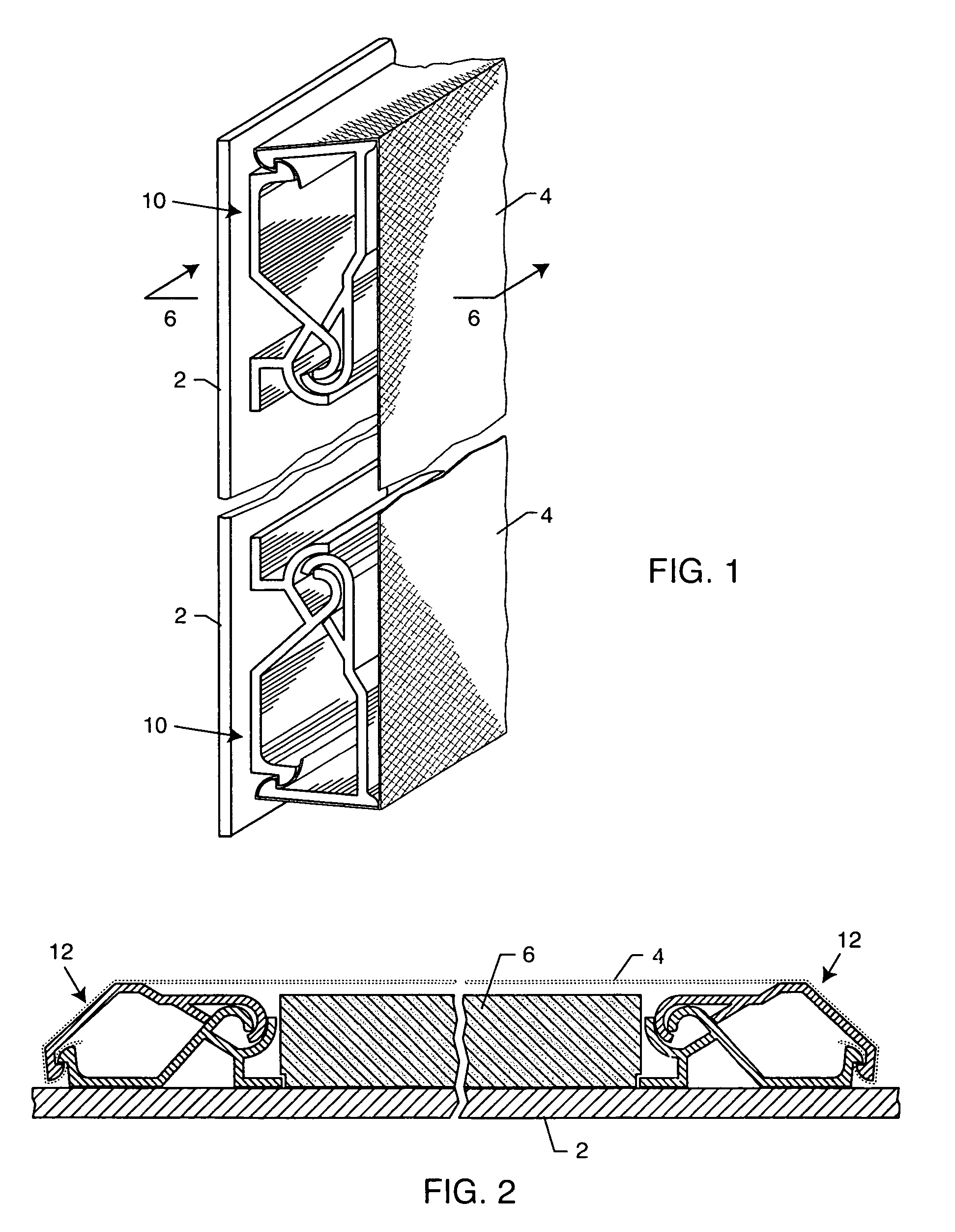
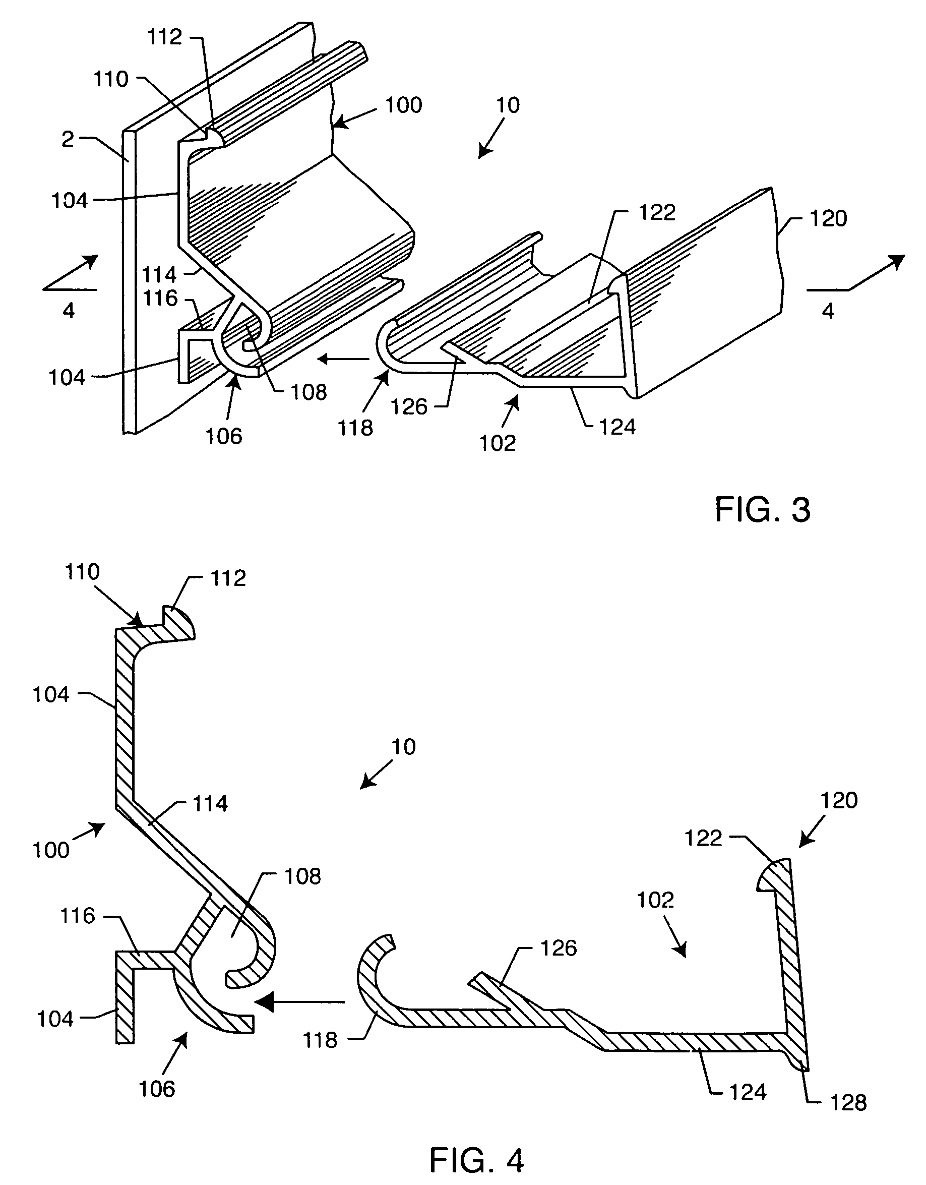
[0036]As shown in the accompanying drawings for purposes of illustration, the present invention resides in a track assembly for covering walls with a fabric or the like. As discussed above, very tight tensioning of fabric panels can impose very high loads on the relatively light-weight hinge and track assembly structures. The spans of fabrics to be stretched can exceed thirty by twenty-five feet, and the fabric panels alone can weigh fifty pounds or more. In the prior art, there was a continuing concern that the fabric could become dislodged from the track assembly due to the tension exerted thereon by the stretched fabrics. Certain track assemblies, particularly those of approximately one-inch thickness, having a generally rectangular closed configuration, could be deformed and moved into a generally parallelogram shape due to the high tension forces of the stretched fabric. As will be more fully described herein, the track assembly of the present invention discloses a design incor...


PUM


Abstract

A track assembly for supporting fabric on a surface includes a base track defining a first half of a hinge and a first half of a snapping clamp. The base track preferably includes a tension force dissipater extending from the first half of the hinge. An upper track defines a second half of the hinge and is pivotally connectable to the base track. The upper track defines a second half of the snapping clamp for releasably engaging the fabric. The upper track includes a strut extended downwardly towards the base track such that when high tension forces are applied to the upper track, due to fabric tensioning, the strut contacts the base track and at least partially transmits the tension forces to the surface.

Description

RELATED APPLICATION[0001]This application claims priority to U.S. Provisional Application Ser. No. 60 / 617,977, filed Oct. 11, 2004; U.S. Provisional Application Ser. No. 60 / 599,563, filed Aug. 5, 2004; and U.S. Provisional Application Ser. No. 60 / 562,966, filed Apr. 16, 2004.BACKGROUND OF THE INVENTION[0002]The present invention generally relates to fabric wall coverings. More particularly, the present invention relates to a track assembly for supporting fabrics on a surface, such as a wall, under high tension, even in thicker assemblies which accommodate acoustical panels and the like.[0003]It is known to provide a framework formed of plastic channeling fastened by means of staples or other means onto the marginal areas of an interior wall to be covered with fabric. U.S. Pat. Nos. 4,403,642 and 6,164,364 disclose track assemblies having two track halves, each having one-half of a hinge and a snapping clamp which interlocks the fabric and clamps the two tracks onto one another. Such...

Claims


Application Information

Patent Timeline
Patent Type & Authority Patents(United States)
IPC IPC(8): E04B1/00E04B9/30E06B3/80
CPCB44C1/10B44D3/185E04B9/303E04F13/005E04B2009/0492
Inventor MORRIS, MILTON A.
Owner MORRIS MILTON A
Why Eureka
Try Eureka