Device for pneumatic control

Inactive Publication Date: 2010-01-26
NORGREN GMBH +1
15 Cites 2 Cited by

AI-Extracted Technical Summary

Problems solved by technology

A particular disadvantage of the known control pistons is that, because of the metallic construction of the control piston, it is necessary to avoid direct contact with the wall of the surrounding cylinder, since otherwise severe...

Method used

[0069]FIG. 6 shows a partial view of a longitudinal section of a high pressure valve (41) with a control piston (49) made entirely of plastic. The control piston (49) consequently only has the seals (54, 63), and can be implemented without guide elem...

Benefits of technology

[0011]An object of an embodiment of the present invention is ...

Abstract

A device used for pneumatic control, includes a control piston carried in a cylinder. The control piston is mounted so as to be movable in the direction of a longitudinal piston axis, and a primary flow path that can be closed by the control pressure passes through the cylinder. The control piston is provided with a control surface that faces a control chamber of the cylinder and that is designed to transmit a control force to the control piston. The control piston is made at least partially of a plastic.

Application Domain

Operating means/releasing devices for valvesServomotor components

Technology Topic

PistonEngineering +3

Image

  • Device for pneumatic control
  • Device for pneumatic control
  • Device for pneumatic control

Examples

  • Experimental program(1)

Example

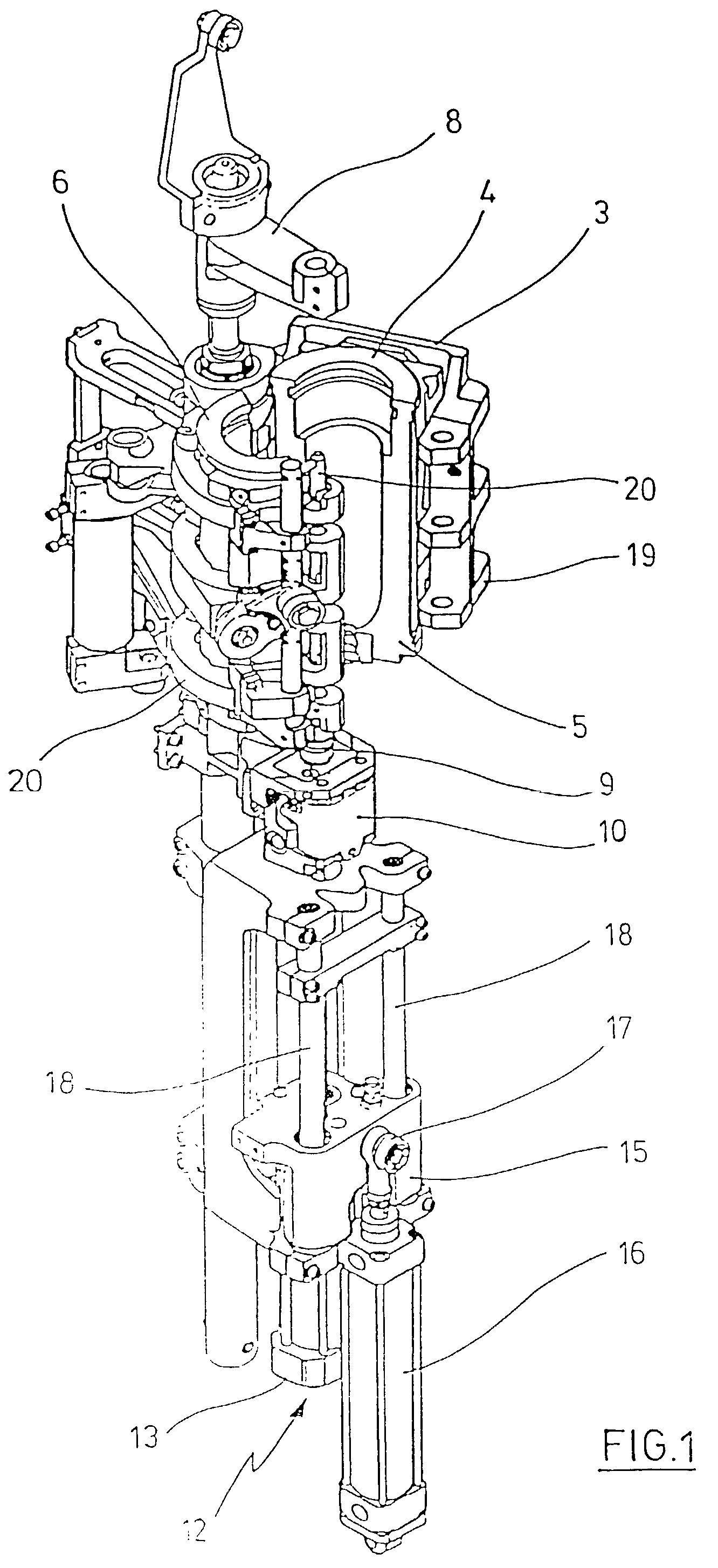
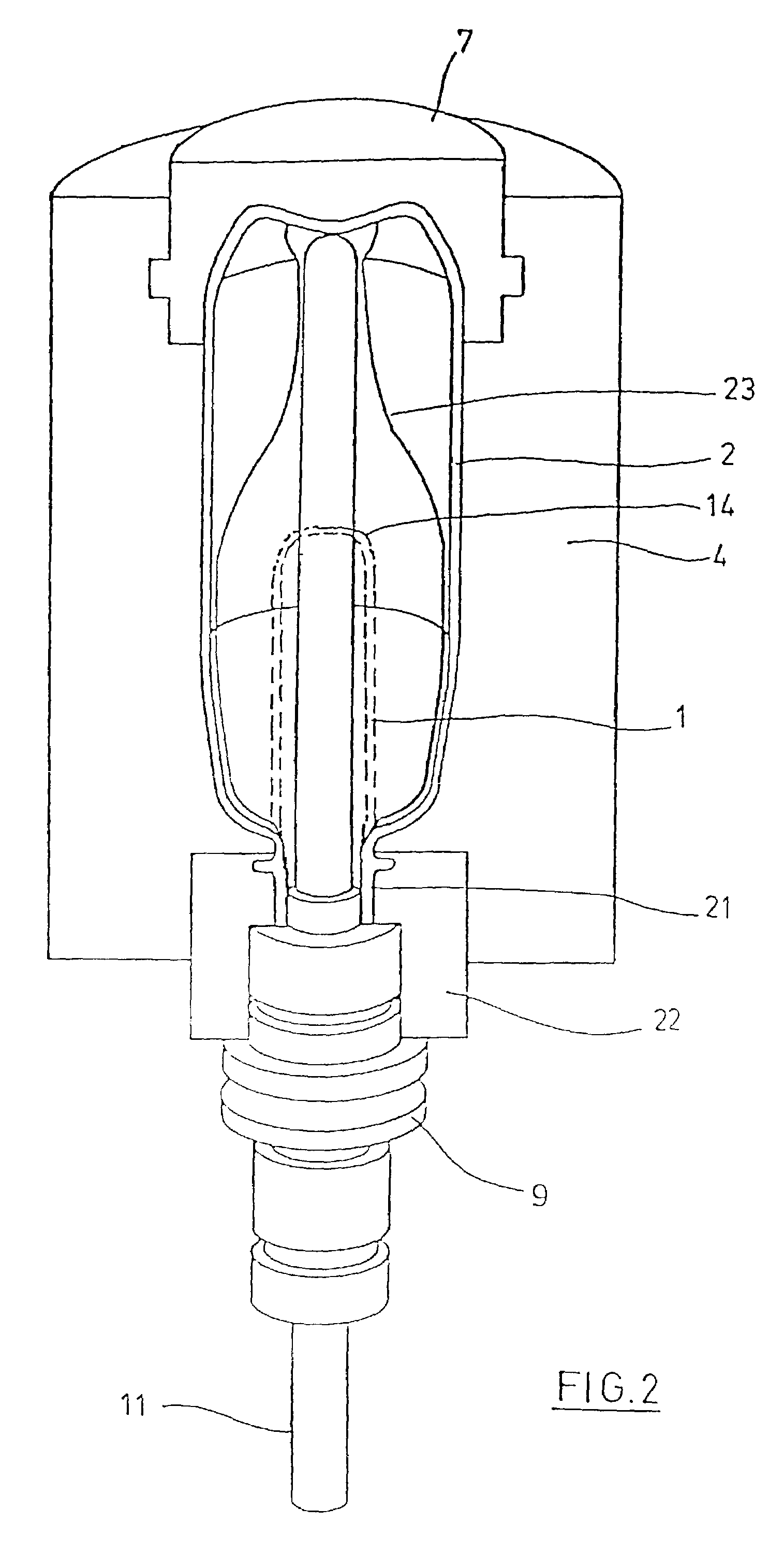
[0041]The device for pneumatic control can for example be used to control the delivery of compressed air in a device for blow molding. The basic structure of a device for forming preforms (1) into containers (2) is shown in FIG. 1 and FIG. 2.
[0042]The device for forming the container (2) consists essentially of a blow station (3), which is equipped with a blow mold (4) into which can be inserted a preform (1). The preform (1) can be an injection-molded part of polyethylene terephthalate. To permit insertion of the preform (1) in the blow mold (4) and to permit removal of the finished container (2), the blow mold (4) is composed of mold parts (5, 6) and a bottom piece (7) that can be positioned by a lifting apparatus (8). The preform (1) can be held in the area of the blow station (3) by a transport mandrel (9), which together with the preform (1) passes through a plurality of treatment stations within the device. However, it is also possible to insert the preform (1) directly in the blow mold (4) through the use of grippers, for example, or other handling devices.
[0043]To permit the delivery of compressed air, a connecting flask (10) is arranged beneath the transport mandrel (9); this flask supplies compressed air to the preform (1) and simultaneously provides sealing relative to the transport mandrel (9). In a modified design, it is also possible to use fixed compressed air lines, of course.
[0044]Stretching of the preform (1) is accomplished with the aid of a stretching rod (11), which is positioned by a cylinder (12). However, it is also possible to accomplish mechanical positioning of the stretching rod (11) by cam segments acted upon by follower rollers. The use of cam segments is particularly useful when a plurality of blow stations (3) are arranged on a rotating blow wheel. Use of cylinders (12) is useful when stationary blow stations (3) are provided.
[0045]In the embodiment shown in FIG. 1, the stretching system is designed such that a tandem arrangement of two cylinders (12) is provided. Before the start of the actual stretching process, the stretching rod (11) is first moved by a primary cylinder (13) into the region of the bottom (14) of the preform (1). During the actual stretching process, the primary cylinder (13) with extended stretching rod is positioned, together with a carriage (15) bearing the primary cylinder (13), by a secondary cylinder.(16) or via a cam control. In particular, the intent is to use cam control of the secondary cylinder (16) in such a way that a current stretching position is given by a guide roll (17), which slides along a curved path during the stretching process. The guide roll (17) is pressed against the guide path by the secondary cylinder (16). The carriage (15) slides along two guide elements (18).
[0046]After the mold parts (5, 6) in the vicinity of supports (19, 20) have closed, the supports (19, 20) lock relative to one another by means of a locking device (20).
[0047]As shown in FIG. 2, provision is made for the use of separate threaded inserts (22) in the area of the blow mould (4) to accommodate the various forms of a mouth section (21) of the preform (1).
[0048]In addition to the blow-molded container (2), FIG. 2 also shows the preform (1), indicated by dashed lines, and a developing container blow (23) in schematic form.
[0049]FIG. 3 shows the basic structure of a blow molding machine that is equipped with a heating section (24) as well as a rotating blow wheel (25). Starting at a preform inlet (26), the preforms (1) are transported by transfer wheels (27, 28, 29) into the area of the heating section (24). Arranged along the heating section (24) are radiant heaters (30) and blowers (31) for temperature treatment of the preforms (1). After sufficient temperature treatment of the preforms (1), they are transferred to the blow wheel (25); the blow stations (3) are arranged near the latter. The finished, blow molded containers (2) are delivered to an output section (32) by additional transfer wheels.
[0050]To be able to mold a preform (1) into a container (2) in such a way that the container (2) has material properties that ensure a long shelf life of foods, more particularly beverages, placed in the container (2), special process steps must be followed during the heating and orientation of the preforms (1). Moreover, beneficial effects can be achieved by adhering to special dimensioning guidelines.
[0051]A variety of plastics can be used as the thermoplastic material. Examples of plastics that may be used include PET, PEN and polypropylene.
[0052]Expansion of the preform (1) during the orientation process is accomplished through the delivery of compressed air. The delivery of compressed air is divided into a preblow phase, in which gas, for example compressed air, is delivered at a low pressure level, and a subsequent primary blow phase, in which gas is delivered at a higher pressure level. Typically, compressed air at a pressure in the range from 10 bar to 25 bar is used during the preblow phase, and compressed air at a pressure in the range from 25 bar to 40 bar is used during the primary blow phase.
[0053]It can also be seen from FIG. 3 that, in the embodiment shown, the heating section (24) is made up of a plurality of circulating transport elements (33) that are linked in the manner of a chain and are carried along by guide wheels (34). In particular, the intent is to cover an essentially rectangular footprint by the chainlike arrangement. In the embodiment shown, a single relatively large guide wheel (34) is used in the vicinity of the portion of the heating section (24) that faces the transfer wheel (29) and a feed wheel (35), and two comparatively small guide wheels (36) are used in the vicinity of adjacent deflections. However, any other desired guide systems are also possible, of course.
[0054]The arrangement shown has proven to be especially useful for facilitating the closest possible arrangement of the transfer wheel (29) and the feed wheel (35) relative to one another, since three guide wheels (34, 36) are positioned in the vicinity of the relevant portion of the heating section (24), in each case with the smaller guide wheels (36) located in the vicinity of the transition to the linear stretches of the heating section (24) and the larger guide wheel located in the immediate transfer region to the transfer wheel (29) and to the feed wheel (35). As an alternative to the use of chain-like transport elements (33), it is also possible to use a rotating heat wheel, for example.
[0055]After blow-molding of the containers (2) is completed, they are removed from the area of the blow station (3) by a discharge wheel (37) and transported to the output section (32) via the transfer wheel (28) and an output wheel (38).
[0056]In the modified heating section (24) shown in FIG. 4, a larger quantity of preforms (1) can be temperature treated per unit time due to the larger number of radiant heaters (30). Here, the blowers (31) direct cooling air to the vicinity of cooling air ducts (39), each of which lies opposite the associated radiant heater (30) and discharges the cooling air through outlet openings. The arrangement of the outlet openings achieves a direction of flow for the cooling air that is essentially perpendicular to the transport direction of the preforms (1). The cooling air ducts (39) can provide reflectors for the radiated heat in the vicinity of the surfaces opposite the radiant heaters (30); it is also possible to implement cooling of the radiant heaters (30) by using the discharged cooling air.
[0057]FIG. 5 shows a vertical section through a device for pneumatic control embodied as a high pressure valve (41). Arranged in a valve base (42) are an inlet channel (43) and an outlet channel (44) that open into an interior cylinder chamber (45), which is at least partially delimited by a cylinder wall (46) of the valve base (42). The section of the inlet channel (43) that faces the interior cylinder chamber (45) provides a primary flow path (47) for the high pressure to be controlled with a flow orifice (48).
[0058]A control piston (49), including primarily a piston shank (50) and a piston head (51), is carried within the interior cylinder chamber (45). The piston shank (50) and the piston head (51) extend essentially symmetrically along a longitudinal piston axis (52), and together form a mushroom-shaped basic structure for the control piston (49).
[0059]The piston shank (50) extends through a piston sleeve (53) held by the valve base (42) and is sealed relative to the piston sleeve (53) with a seal (54). The seal (54) can take the form of an O-ring, for example.
[0060]In the embodiment shown, the piston shank (50) has a cross-sectional area (55) that is dimensioned essentially the same as the flow orifice (48). In the embodiment shown in FIG. 5, a shank cap (56) is placed on the piston shank (50) in the section that faces away from the piston head (51). In particular, the intent is to secure the shank cap (56) with a ridge (57) in a groove (58) of the piston shank (50). In an especially simple fashion, this can be accomplished in the form of a snap-on connection if the shank cap (56) implementation is sufficiently elastic.
[0061]The piston head (51) has, in the section that faces away from the piston shank (50), a control surface (59) that can be acted upon by a control pressure for positioning the control piston (49) within the interior cylinder chamber (45). Extending adjacent to the control surface (59) is a control chamber (60), into which discharges a feed line (61) for the control pressure.
[0062]The control chamber (60) is partially delimited by a cylinder head (62) that is held by the valve base (42). The piston head (51) is sealed relative to an inner wall of the cylinder head (62) by a seal (63). To ensure end point damping during positioning of the control piston (49), a damping element (64) can be inserted in the piston head (51).
[0063]In order to provide a compact embodiment, it is possible to place a cylinder fairing (65) or a spacer strap on the cylinder head (62) to protect the upper section of the cylinder head (62) from external mechanical stresses. When the control piston (49) is made partially of metal, guide elements (66) of plastic or similar soft materials are used in addition to the seals (54, 63) in order to prevent metal-to-metal contact between the control piston (49) and the cylinder wall (46), which likewise generally is made of metal, or the cylinder sleeve (53).
[0064]FIG. 5 shows the high pressure valve (41) with the primary flow path (47) in a closed state. The piston shank (50) is placed, with the shank cap (56), against the edge of the primary flow path (47) and seals the interior cylinder chamber (45) from the primary flow path (47). In the area of the control chamber (60), a control pressure is present that acts upon the control surface (59) and generates a force acting on the control piston (49) that is greater than the force from the primary pressure acting on the shank cap (56). Reliable closing of the high pressure valve (41) is ensured by this means. When the control pressure drops, the control piston (49) is moved in the direction of the longitudinal piston axis (52) by the high pressure, and the high pressure can escape from the primary flow path (47) through the interior cylinder chamber (47) into the region of the outlet channel (44). As a result, the high pressure valve (41) is in an open state.
[0065]When the control pressure rises again, the control piston (49) returns to the original position and seals the primary flow path (47) again. Because the cross-sectional area (55) of the piston shank (50) and the flow orifice (48) of the primary flow path (47) have essentially equal dimensions in the embodiment shown, essentially the same forces with regard to the high pressure act on the control piston (49) in both the open and closed states of the high pressure valve (41). As a result, essentially the same control forces are required for closing the valve as for holding the valve closed.
[0066]In accordance with a preferred embodiment, the intent is to construct the control piston (49) completely of plastic. The guide elements (66) can then be eliminated entirely. A further intent is to implement the piston shank (50) and the piston head (51) together and in a single piece from the same plastic. For example, PETP can be used here. In the event of a partially metal embodiment, use of aluminum, in particular, is intended.
[0067]Plastic is used preferentially for implementation of the shank cap (56), as well. Here, too, use of PETP, for example, is intended.
[0068]In accordance with typical dimensioning in an application for the switching of blow pressures, the piston head (51) is given a diameter of approximately 50 mm. A typical diameter of the piston shank (50) is approximately 14 mm to 20 mm, especially 18 mm, and a typical diameter of the flow orifice (48) is likewise approximately 14 mm to 20 mm, especially 18 mm. With such dimensioning, a control pressure of less than 10 bar generally proves sufficient for switching a primary pressure of maximum 40 bar.
[0069]FIG. 6 shows a partial view of a longitudinal section of a high pressure valve (41) with a control piston (49) made entirely of plastic. The control piston (49) consequently only has the seals (54, 63), and can be implemented without guide elements (66). It can also be seen in FIG. 6 that seals (67) are arranged between the piston sleeve (53) and the valve base (42) or cylinder head (62), in order to ensure a highly effective seal. The seals (67) can be implemented as O-rings, for example.
[0070]FIG. 7 again illustrates the arrangement of the shank cap (56) in the vicinity of the piston shank (50), as well as the arrangement of groove-like indentations in the control piston (49) and in the vicinity of the piston sleeve (53) to accommodate the seals (54, 63, 67). To make it possible for the interior cylinder chamber (45) to have small dimensions in the direction of the longitudinal piston axis (52), in the embodiment shown in FIG. 7 an indentation (68) is arranged in the vicinity of the piston sleeve (53) to accommodate the shank cap (56) in the open state of the high pressure valve (41).
[0071]The invention being thus described, it will be obvious that the same may be varied in many ways. Such variations are not to be regarded as a departure from the spirit and scope of the invention, and all such modifications as would be obvious to one skilled in the art are intended to be included within the scope of the following claims.

PUM

PropertyMeasurementUnit
Pressure1000000.0Pa
Pressure4000000.0Pa
Fraction2.0fraction

Description & Claims & Application Information

We can also present the details of the Description, Claims and Application information to help users get a comprehensive understanding of the technical details of the patent, such as background art, summary of invention, brief description of drawings, description of embodiments, and other original content. On the other hand, users can also determine the specific scope of protection of the technology through the list of claims; as well as understand the changes in the life cycle of the technology with the presentation of the patent timeline. Login to view more.
Why Eureka
Try Eureka