
Method and apparatus for harvesting biomechanical energy

a biomechanical energy and energy harvesting technology, applied in the direction of machines/engines, prostheses, gymnastics, etc., can solve the problems of limited commercial viability or success, limited power generation capacity of energy harvesting apparatus disclosed by these authors, and relatively high metabolic energy cost,

Inactive Publication Date: 2010-01-26
DONELAN JAMES MAXWELL +4
View PDF113 Cites 67 Cited by
  • Summary
  • Abstract
  • Description
  • Claims
  • Application Information

AI Technical Summary

Problems solved by technology

For a variety of reasons, the energy harvesting apparatus disclosed by these authors have experienced limited power generation capacity and / or limited commercial viability or success.
Drawbacks of the prior art energy harvesting apparatus contemplated in these disclosures include: lack of implementation detail; low power yield; and heavy and / or awkward energy harvesting apparatus, which can lead to relatively high metabolic energy costs and correspondingly low energy conversion efficiency and / or impairment of normal physical activity, for example.

Method used


Image

  • Method and apparatus for harvesting biomechanical energy
  • Method and apparatus for harvesting biomechanical energy
  • Method and apparatus for harvesting biomechanical energy

Examples


Embodiment Construction

[0063]Throughout the following description, specific details are set forth in order to provide a more thorough understanding of the invention. However, the invention may be practiced without these particulars. In other instances, well known elements have not been shown or described in detail to avoid unnecessarily obscuring the disclosure. Accordingly, the specification and drawings are to be regarded in an illustrative, rather than a restrictive, sense.

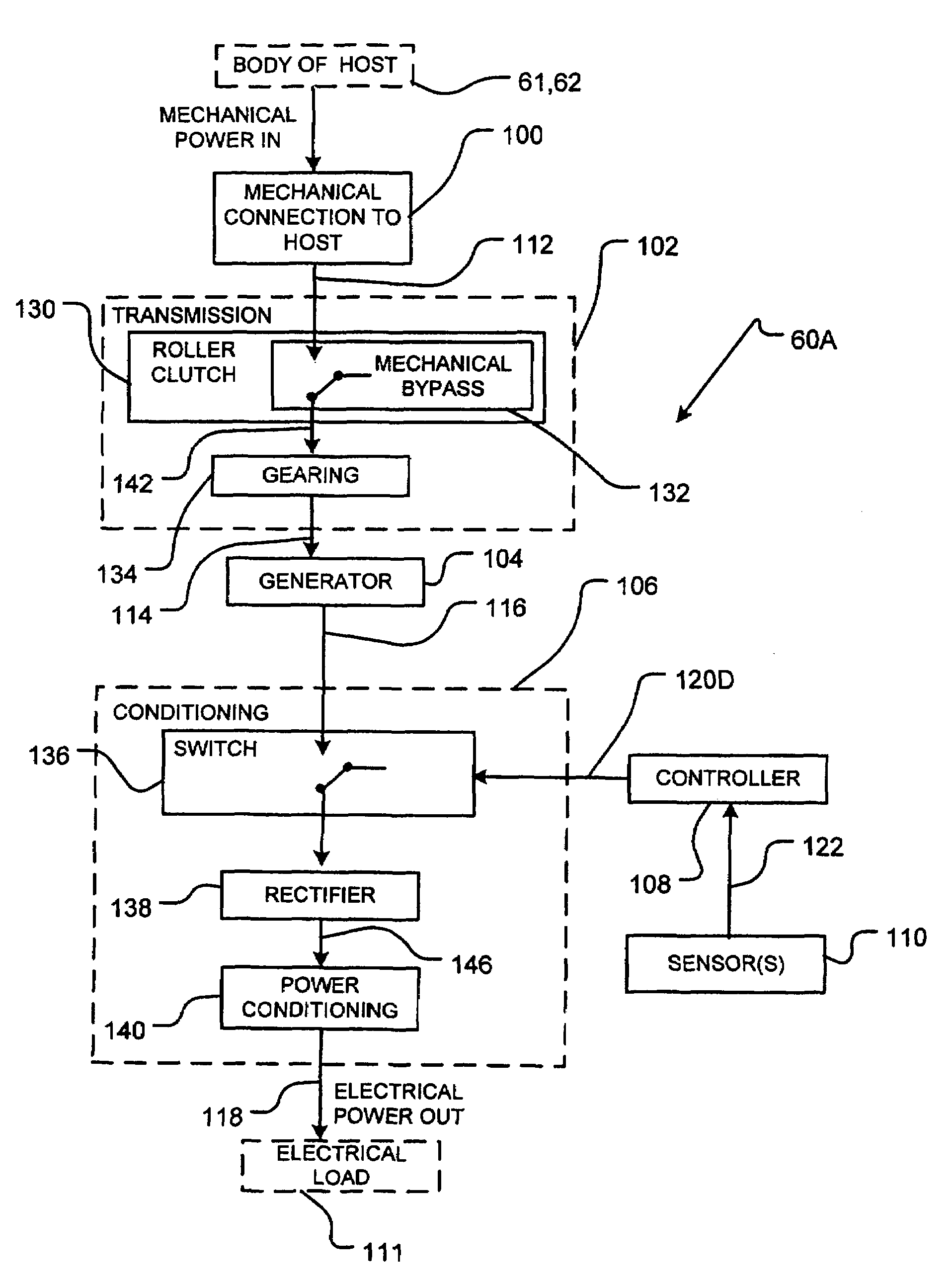
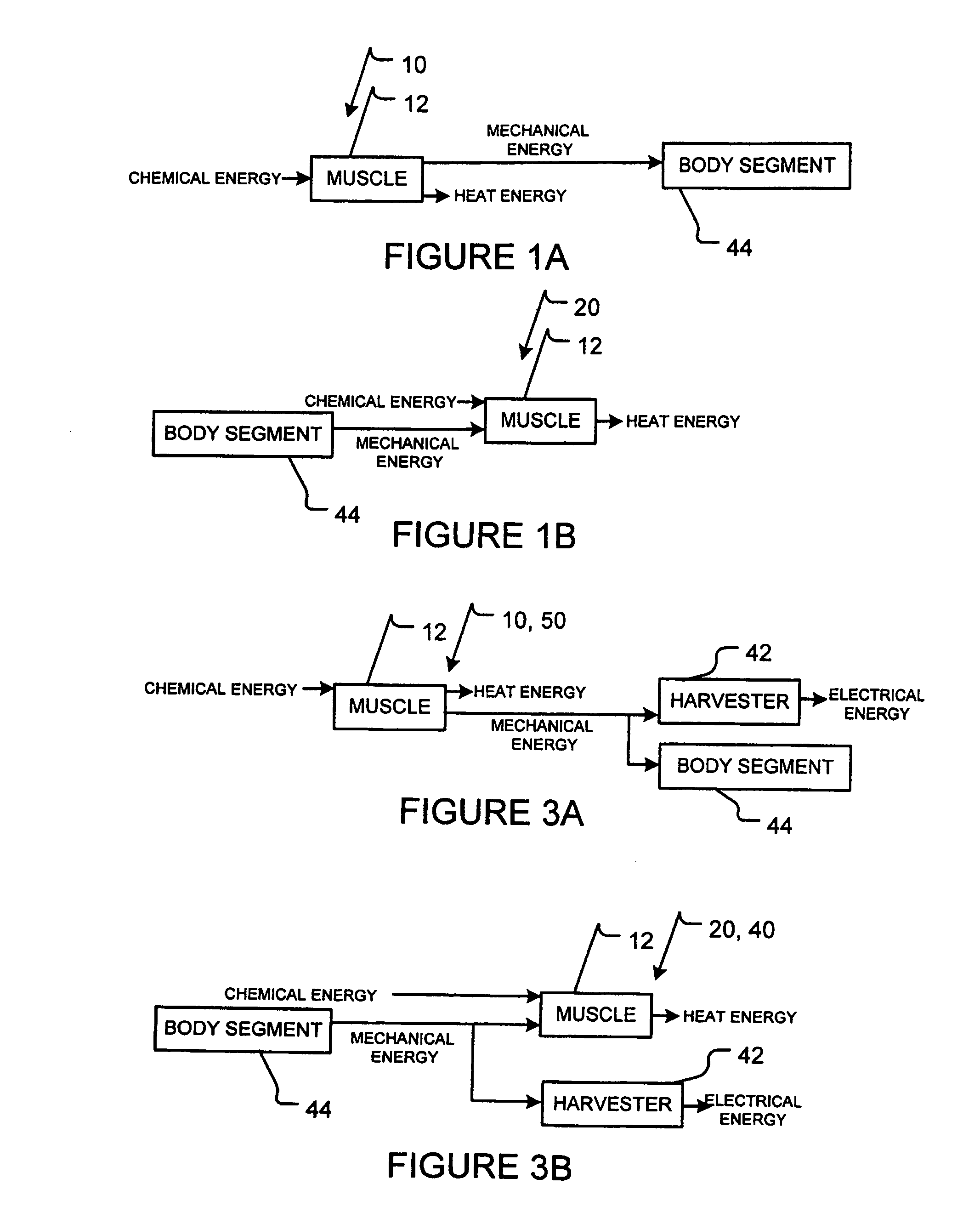
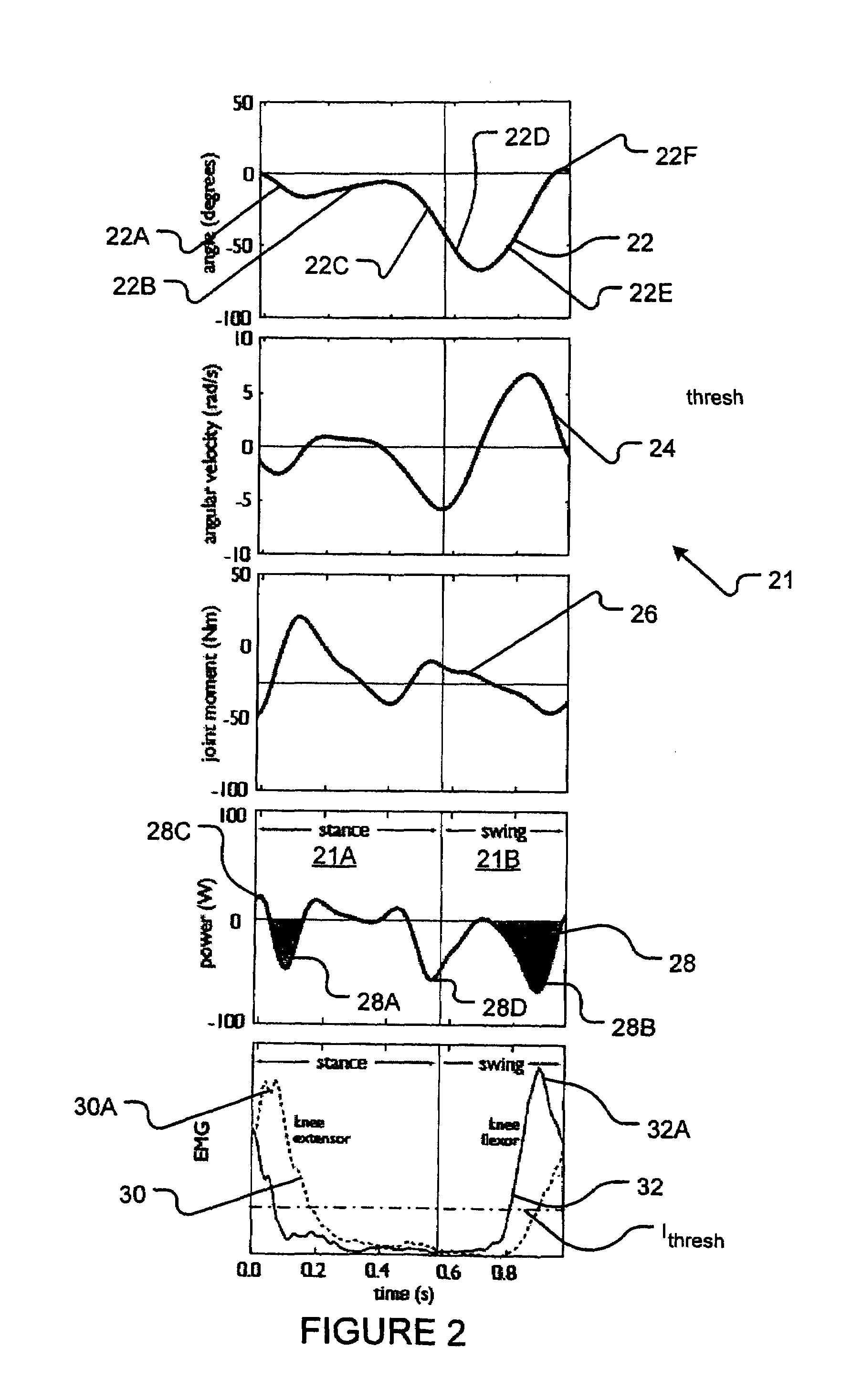
[0064]FIG. 1A schematically depicts a positive mechanical power operational mode 10 of a muscle 12, wherein muscle 12 is used to generate mechanical energy which results in corresponding movement of one or more associated body segment(s) 44 (e.g. limb(s)). In positive mechanical power mode 10, muscle 12 converts chemical energy into mechanical energy of associated body segment 44. Due to the inefficiency of this conversion process, muscle 12 also outputs heat energy when operating in positive mechanical power mode 10. Positive mechan...


PUM


Abstract

Methods and apparatus are disclosed for harvesting energy from motion of one or more joints. Energy harvesters comprise: a generator for converting mechanical energy into corresponding electrical energy; one or more sensors for sensing one or more corresponding characteristics associated with motion of the one or more joints; and control circuitry connected to receive the one or more sensed characteristics and configured to assess, based at least in part on the one or more sensed characteristics, whether motion of the one or more joints is associated with mutualistic conditions or non-mutualistic conditions. If conditions are determined to be mutualistic, energy harvesting is engaged. If conditions are determined to be non-mutualistic, energy harvesting is disengaged.

Description

CROSS-REFERENCE TO RELATED APPLICATIONS[0001]This application is a continuation of U.S. patent application Ser. No. 11 / 990,165, filed Feb. 8, 2008, which application is the national stage application of PCT / CA2006 / 001302, filed Aug. 10, 2006, which claims the benefit of U.S. Provisional App. No. 60 / 707,232, filed Aug. 10, 2005.TECHNICAL FIELD[0002]This invention relates to methods and apparatus for converting mechanical energy generated by humans and / or animals into electrical energy. Harvested electrical energy can be used for a variety of purposes.BACKGROUND OF THE INVENTION[0003]Humans and other animals are a rich source of mechanical power. In general, this mechanical power is derived from chemical energy. The chemical energy required for a muscle or group of muscles to perform a given activity may be referred to as the “metabolic cost” of the activity. In humans and other animals, chemical energy is derived from food. Food is generally a plentiful resource and has a relatively ...

Claims


Application Information

Patent Timeline
Patent Type & Authority Patents(United States)
IPC IPC(8): F02B63/04F03G7/08H02K7/18A61F2/48A61H1/00A61H1/02A61H5/00A63B21/002
CPCF03G5/00F03G5/06H02K7/1853A61F2002/708F03G5/086F03G5/063F03G5/061
Inventor DONELAN, JAMES M.KUO, ARTHUR D.HOFFER, JOAQUIN A.LI, QINGGUOWEBER, DOUGLAS
Owner DONELAN JAMES MAXWELL
Learn More