Circuits and methods for improving slew rate of differential amplifiers

a differential amplifier and circuit technology, applied in the field of high-speed operational amplifiers, can solve the problems of increased power dissipation, decreased stability and oscillation of output voltage, and output signal slewing, so as to improve slew rate, improve slew rate, and reduce power dissipation

Active Publication Date: 2010-01-26
SAMSUNG ELECTRONICS CO LTD
View PDF10 Cites 42 Cited by
  • Summary
  • Abstract
  • Description
  • Claims
  • Application Information

AI Technical Summary

Benefits of technology

[0017]In general, exemplary embodiments of the invention include high speed operational amplifiers having frequency compensation circuits that provide improved slew rates with low power dissipation. More specifically, exemplary embodiments of the invention including frequency compensation circuits implementing miller compensation, which are dynamically configured to change nodal connections of compensation capacitors during driver setup and driving periods to provide improved slew rates, while providing stable operation with low power dissipation.

Problems solved by technology

However, the addition of the compensation capacitors introduces slewing of the output signal as a result of the time delay for charging and discharging the capacitors when driving the output node NOUT.
Reducing the size of compensation capacitors C1 and C2, however, results in decreased stability and oscillation of the output voltage, which is undesirable.
Although the bias currents can be increased to improve the slew rate, this is undesirable as increased bias current levels result in increased power dissipation.

Method used


Image

  • Circuits and methods for improving slew rate of differential amplifiers
  • Circuits and methods for improving slew rate of differential amplifiers
  • Circuits and methods for improving slew rate of differential amplifiers

Examples


Embodiment Construction

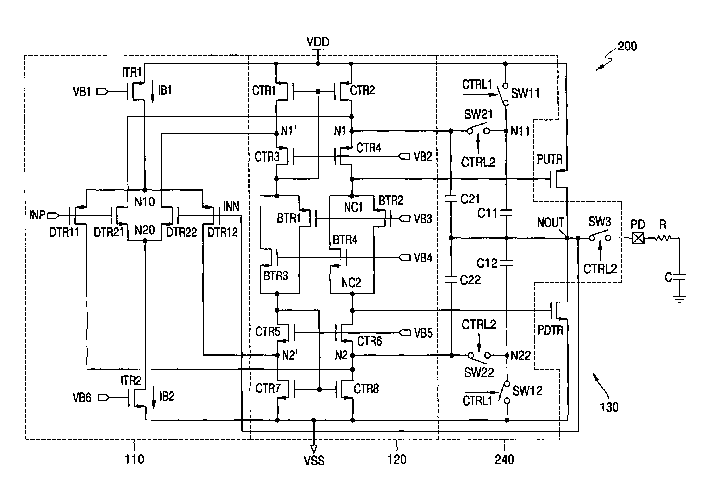
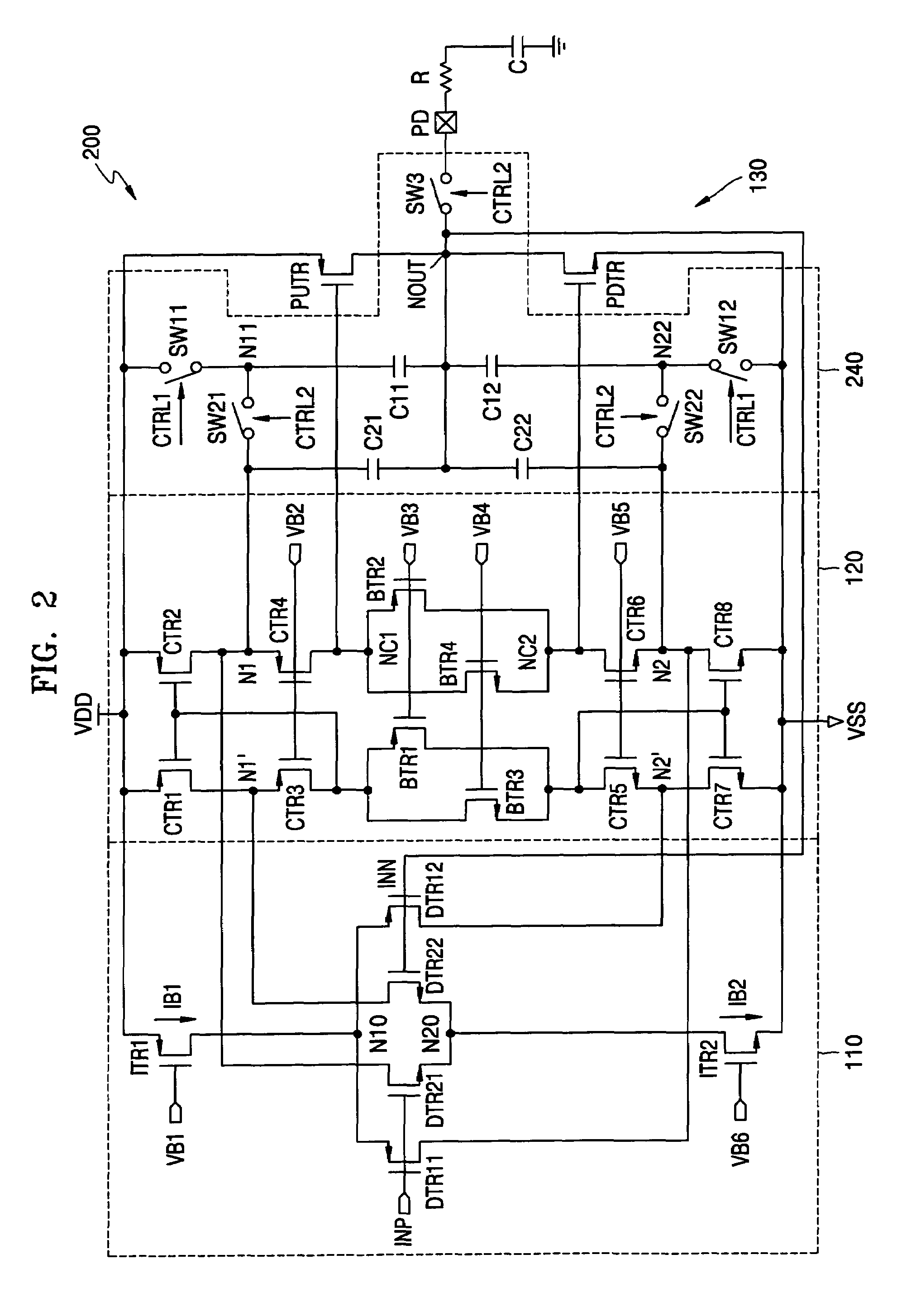
[0032]FIG. 2 illustrates an operational amplifier (200) according to an exemplary embodiment of the invention. The operational amplifier (200) has a framework similar to the operational amplifier (100) of FIG. 1, except that the operational amplifier (200) comprises a frequency compensation circuit (240) that is designed to improve the slew rate without increasing static power consumption. In general, the operational amplifier (200) comprises a first supply voltage (VDD) rail and a second supply voltage (VSS) rail, a differential amplifier input stage (110) comprising a non-inverting input terminal INP and an inverting signal input terminal INN, a folded cascode stage (120) connected to an output of the differential amplifier input stage (110), and a class AB output driver stage (130) for generating a driving current to drive output node NOUT. The various stages (110, 120 and 130) are similar in architecture and operation to the operational amplifier of FIG. 1 and, thus, a detailed ...


PUM


Abstract

Circuits and methods are provided for providing high speed operational amplifiers and, in particular, operational amplifiers having frequency compensation circuits that provide improved slew rates with low power dissipation when configured with feedback. Frequency compensation schemes are provided to enable dynamic configuration of frequency compensation circuits implementing miller compensation whereby nodal connections of compensation capacitors are changed during driver setup and driving periods such that compensation capacitors are connected to source voltages to rapidly charge / discharge compensation capacitors using supply source currents during setup period, while providing frequency compensation during the setup and driving periods to maintain circuit stability and prevent oscillation of an output voltage due to the feedback.

Description

CROSS-REFERENCE TO RELATED APPLICATION[0001]This application claims priority to Korean Patent Application No. 10-2004-0077156, filed on Sep. 24, 2004, which is incorporated herein by reference.TECHNICAL FIELD OF THE INVENTION[0002]The present invention relates generally to high speed operational amplifiers and, more specifically, to differential amplifiers having frequency compensation circuits that provide improved slew rates with low power dissipation.BACKGROUND[0003]In general, operational amplifiers are versatile integrated circuits that are commonly implemented in various types of electronic circuits. For instance, operational amplifiers are typically used as output drivers for LCD (liquid crystal display) devices, DACs (digital-to-analog converters), ADCs (analog-to-digital converters), switched capacitor filters, analog filters, etc. In LCD devices, source driver circuits are constructed using operational amplifiers as source line drivers for driving an output signal to trans...

Claims


Application Information

Patent Timeline
Patent Type & Authority Patents(United States)
IPC IPC(8): H03F1/14
CPCH03F1/08H03F1/34H03F3/3022H03F3/45192H03F3/45475H03F2203/45534H03F2203/45248H03F2203/45264H03F2203/45366H03F2203/45514H03F2203/45226H03F3/45
Inventor CHOI, YOON-KYUNG
Owner SAMSUNG ELECTRONICS CO LTD
Why Eureka
Try Eureka