Method of resin sealing permanent magnets in laminated rotor core

a technology of laminated rotor core and permanent magnet, which is applied in the field of resin sealing permanent magnets in laminated rotor core, can solve the problems of reducing the fluidity reducing the temperature of the resin material, and the method having difficulty in filling the resin material into the magnet insertion holes, etc., to achieve the effect of improving product quality, improving the efficiency of filling operation of the resin material into the laminated rotor core, and simplifying the apparatus

Active Publication Date: 2010-02-02
MITSUI HIGH TEC INC
View PDF24 Cites 24 Cited by
  • Summary
  • Abstract
  • Description
  • Claims
  • Application Information

AI Technical Summary

Benefits of technology

[0009]In the method according to the present invention, the laminated rotor core is placed and preheated in the preheating device before being disposed between the upper and lower dies of the resin sealing apparatus used for filling the resin material into the magnet insertion holes. Accordingly, filling the resin material into the magnet insertion holes can be immediately started by removing the preheated laminated rotor core from the preheating device and disposing the core between the upper and lower dies. As a result, the filling operation of the resin material is less affected by progress of preheating of the laminated rotor core and efficiency of filling operation of the resin material into the laminated rotor core is greatly improved compared with a conventional case where preheating of the laminated rotor core and filling of the resin material are performed in the same device.
[0010]Furthermore, since the laminated rotor core is preheated, liquefying of the resin material (liquefying of tablet-shaped raw material of the resin material) and filling and curing thereof are performed efficiently after the laminated rotor core is disposed between the upper and lower dies, and product quality is improved compared with conventional methods.
[0011]In the method according to the present invention, it is preferable that the resin reservoir pots in either one of the upper and lower dies of the resin sealing apparatus are formed in a region located radially inward or outward with respect to the magnet insertion holes so that the resin material is filled into the magnet insertion holes from the resin reservoir pots via resin passages formed in either one of the resin sealing apparatus and the laminated rotor core. In this instance, the liquefied resin material in each of the resin reservoir pots is supplied to corresponding one or two (three or more according to circumstances) of the magnet insertion holes via the resin passages, which allows simplification of the apparatus. In addition, the resin reservoir pots are preferably formed penetrating either one of the upper and lower dies.
[0012]In the method according to the present invention, it is preferable that the preheating of the laminated rotor core in the first process is performed with the permanent magnets inserted in the magnet insertion holes. Consequently, preheating of the laminated rotor core and of the permanent magnets can be carried out simultaneously. Depending on the type of the permanent magnets, magnetism of the permanent magnets may be decreased by heat. When such permanent magnets are used, the laminated rotor core and the permanent magnets may be heated separately. In this case, the permanent magnets are heated to an appropriate temperature (e.g., in a range of 100 to 160° C.) and then are inserted in the magnet insertion holes of the laminated rotor core heated to a higher temperature. The preheating temperature of the laminated rotor core may be equal to a melting temperature of the resin (e.g., in a range of 150 to 180° C.), or may be within a band of plus or minus 20° C. of the melting temperature. Higher preheating temperatures of the laminated rotor core would increase fluidity of the resin material in the laminated rotor core, thereby shortening the filling time and improving productivity. Lower preheating temperatures of the laminated rotor core would reduce deformation of the laminated rotor core caused by heating, but may cause incomplete filling of the resin material depending on the structure of the laminated rotor core. Therefore, it is preferable to set an appropriate preheating temperature according to the shape and height of the laminated rotor core.
[0013]In the method according to the present invention, the preheating of the laminated rotor core in the first process may be performed without the permanent magnets inserted in the magnet insertion holes, and the permanent magnets may be inserted in the magnet insertion holes after completion of the preheating of the laminated rotor core. In this instance, because the permanent magnets are not directly heated by a heat source, deterioration of the permanent magnets due to excessive heating is prevented.

Problems solved by technology

Therefore, the temperature of the resin material is reduced when the resin material melted by heating is filled into the magnet insertion holes, which disadvantageously reduces fluidity of the resin material.
Accordingly, the conventional method has difficulty in filling the resin material into the magnet insertion holes and also in curing the resin material filled in the magnet insertion holes.
However, since the melting temperature of the resin material (e.g., an epoxy resin) is as high as around 170° C., for example, it takes several dozens of minutes for the laminated rotor core to reach the melting temperature of the resin material.
Accordingly, filling operation of the resin material is greatly affected by preheating operation of the core by the heaters of the upper and lower dies, which greatly reduces operating efficiency of filling of the resin material (productivity of the resin sealing apparatus).

Method used


Image

  • Method of resin sealing permanent magnets in laminated rotor core
  • Method of resin sealing permanent magnets in laminated rotor core
  • Method of resin sealing permanent magnets in laminated rotor core

Examples


Embodiment Construction

[0022]Referring now to the accompanying drawings, embodiments of the present invention will be described for a more complete understanding of the invention.

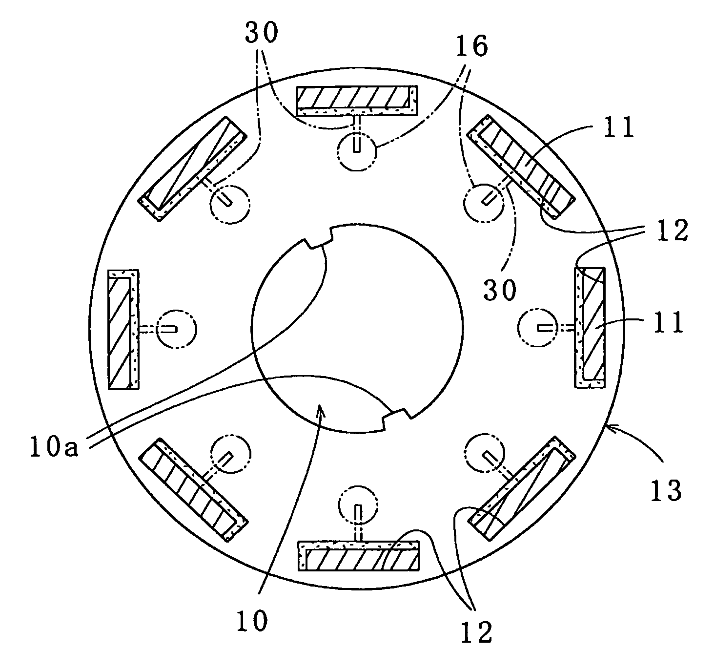
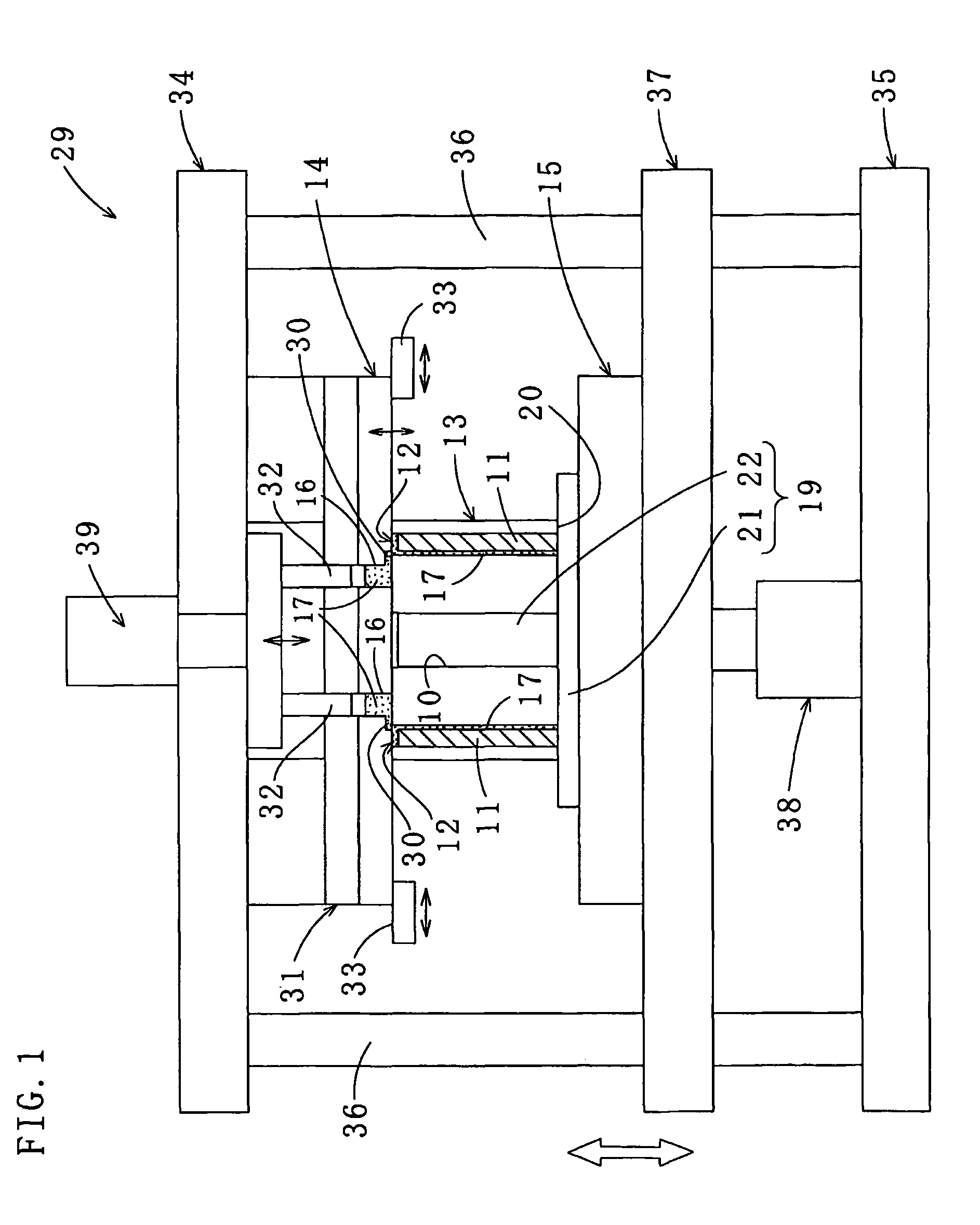
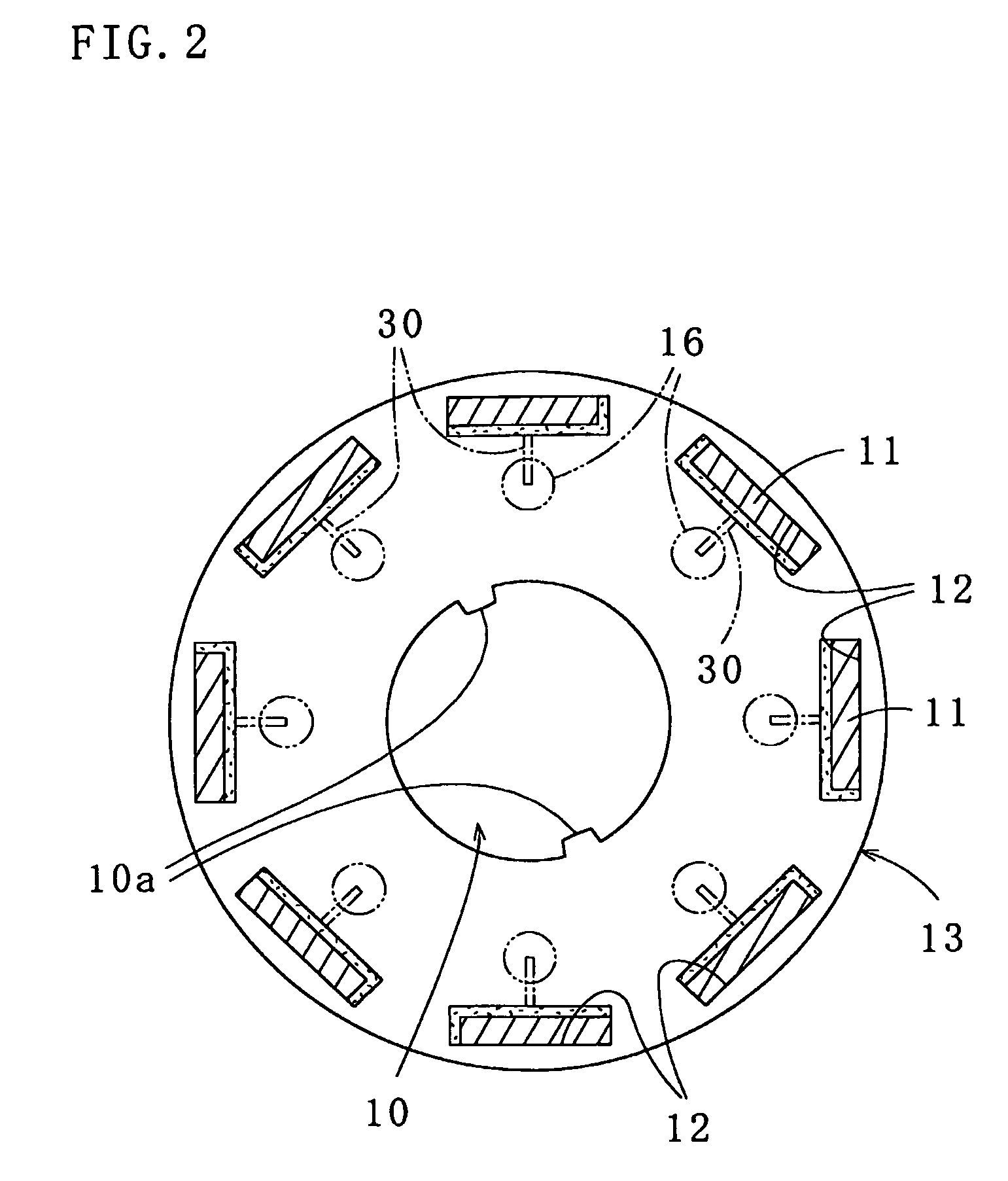
[0023]As illustrated in FIGS. 1 through 4, a method of resin sealing permanent magnets in a laminated rotor core according to a first embodiment of the present invention includes a step of preheating a laminated rotor core (also referred to as a rotor) 13 in the vicinity of a prescribed temperature before resin sealing permanent magnets 11 respectively in a plurality of magnet insertion holes 12 formed on a circumferential part of the laminated rotor core 13, thereby improving efficiency of a subsequent resin sealing operation. The resin sealing of the permanent magnets 11 is effected as follows. The laminated rotor core 13 having the permanent magnets 11 in the respective magnet insertion holes 12 is clamped with the upper and lower dies 14 and 15 of a resin sealing apparatus 29, and resin material 17 is filled into the magnet i...


PUM

PropertyMeasurementUnit
melting temperatureaaaaaaaaaa
temperatureaaaaaaaaaa
melting temperatureaaaaaaaaaa

Abstract

A method comprising: a first process of placing a laminated rotor core (13) in a preheating device (18) to preheat the laminated core (13); a second process of removing the preheated laminated core (13) from the preheating device (18) and disposing the laminated core (13) between upper and lower dies (14, 15) of a resin sealing apparatus (29); a third process of pressing the laminated core (13) by the upper and lower dies (14, 15) and liquefying resin material (17) in resin reservoir pots (16) by heating; and a fourth process of ejecting the liquefied resin material (17) from the pots (16) into the magnet insertion holes (12) by plungers (32) inserted and moving vertically in the pots (16) and thermally curing the resin material (17). The method improves efficiency of resin sealing the permanent magnets (11) in the laminated core (13).

Description

[0001]This application claims the priority of Japanese Foreign Application No. 2006-003867, filed Jan. 11, 2006 and PCT Application Ser. No. JP2006 / 311162, filed May 29, 2006; the disclosures of which are incorporated by reference in their entirety.Technical Field[0002]The present invention relates to a method of resin sealing permanent magnets in a laminated rotor core by fixing the permanent magnets with resin material.Background Art[0003]Conventionally, as one of methods for fixing permanent magnets to a laminated rotor core used in a motor, a method of fixing permanent magnets with resin material has been proposed. Such a method is disclosed, for example, in Japanese Patent Application Laid-Open Publication No. 2002-34187, comprising the steps of: placing a laminated rotor core in a resin sealing apparatus (also referred to as resin filling apparatus) having upper and lower dies, the laminated rotor core being formed by stacking a plurality of core pieces and having a plurality ...

Claims


Application Information

Patent Timeline
Patent Type & Authority Patents(United States)
IPC IPC(8): H02K15/03
CPCB29C45/02B29C45/14778H02K15/12H02K1/276B29K2995/0008H01F41/0233Y10T29/49078Y10T29/49009Y10T29/49075Y10T29/49012
Inventor AMANO, KATSUMIUEDA, KAZUTOSHI
Owner MITSUI HIGH TEC INC
Why Eureka
Try Eureka