Anti-freezing hydrant

a technology of anti-freezing hydrants and hydrants, which is applied in the direction of drawing-off water installations, thin material handling, construction, etc., can solve the problems of poor leakage blocking effect, and achieve the effect of good sealing and relatively high warning accuracy

Inactive Publication Date: 2010-02-02
LONG TAI COPPER
View PDF2 Cites 4 Cited by
  • Summary
  • Abstract
  • Description
  • Claims
  • Application Information

AI Technical Summary

Benefits of technology

[0007]In the anti-freezing hydrant according to this invention, the rubber cushion of one-way valve may be well deformed and thus seals the inner water inlet; even if being blocked by the foreign matters, it may be a good sealant. Besides, the area of contact of the inner cone with the inclined cone of the back pressure stopper is larger, the accuracy of warning may also be relatively higher.

Problems solved by technology

The O-shaped ring 141 is subject to and blocked with foreign matters and thus cannot fully block water, thereby providing poor effect of leakage blocking.

Method used


Image

  • Anti-freezing hydrant
  • Anti-freezing hydrant
  • Anti-freezing hydrant

Examples


Embodiment Construction

[0015]Now, the present invention will be described more specifically with reference to the following embodiments. It is to be noted that the following descriptions of preferred embodiments of this invention are presented herein for purpose of illustration and description only; it is not intended to be exhaustive or to be limited to the precise form disclosed.

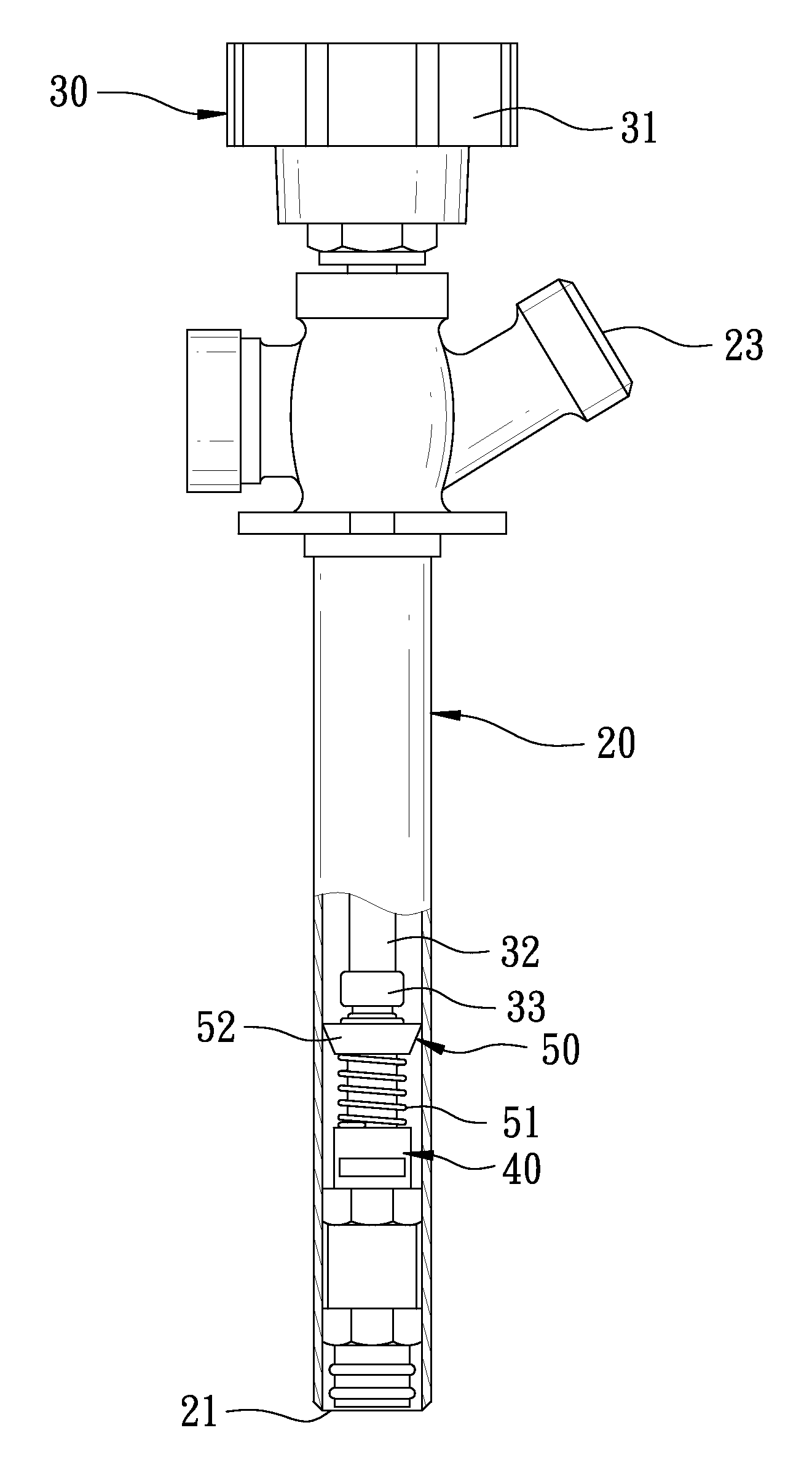
[0016]Firstly, with reference to FIGS. 3 through 5 respectively as a assembly semblance view, an exploded view, and a partially sectional view illustrating an anti-freezing hydrant in a preferred embodiment of this invention, the anti-freezing hydrant comprises an outer tube 20, a handle knob 30, a valve 40, and a back pressure device 50.

[0017]One end of the outer tube 20 is provided with a water inlet 21 and the other end is provided with a joint port 22 and a water outlet 23.

[0018]In the handle knob 30, a handlebar 31 is connected to the joint port 22. The handlebar 31 is provided with a hollow valve rod 32 of which an end is ...


PUM


Abstract

An anti-freezing hydrant is provided with a hollow valve rod of which a back end is provided with a lump formed with an oblique cone where a water leakage hole is formed communicating with the valve rod. A one-way valve is provided in a inner water inlet in a valve chamber of a valve and comprises a rubber cushion being made of a soft rubber and thus elastically suppressing the inner water inlet. The bore of a back pressure stopper in a back pressure is a complement of an inner inclined cone with the oblique cone. Thus, the rubber cushion may enhance the capability of sealing of the valve. Further, the back pressure stopper may also be a good sealant for the inclined cone.

Description

BACKGROUND OF THE INVENTION[0001]1. Field of the Invention[0002]This invention relates to the structure of a hydrant and particularly to a anti-freezing hydrant.[0003]2. Description of Related Art[0004]Refer to FIG. 1 as an exploded view illustrating the appearance of a conventional anti-freezing hydrant. The anti-freezing hydrant 10 mainly comprises an outer tube 11; one end of the outer tube 11 is provided with a water inlet 111 and the other end is provided with a joint port 112 and a water outlet 113. A handle knob 12 and a valve 13 are assembled in the joint port 112. The handle knob 12 is assembled onto the joint port 112 and may revolve the valve 13 to valve the water inlet 111 or the water outlet 113. In order to follow the standard of ASSE-1019A, refer to FIG. 2. A back pressure valve 14 is provided in the valve 13 for water to flow from the water inlet 111 in a single way. Further, the handle knob 12 is provided with a hollow valve rod 121 of which an end is provided with ...

Claims


Application Information

Patent Timeline
Patent Type & Authority Patents(United States)
IPC IPC(8): E03B9/02E03B9/14
CPCE03B7/10E03B9/14Y10T137/1244Y10T137/1353Y10T137/5497
Inventor WU, FAUCET
Owner LONG TAI COPPER
Why Eureka
Try Eureka