Digital voltage converter with constant off-time and variable on-time of controller

a digital voltage converter and controller technology, applied in the field of digital voltage converters, can solve the problems of large ripple at the output vo, more implementation cost, limited by, etc., and achieve the effect of reducing output ripple and high duty-ratio

Inactive Publication Date: 2010-02-02
RICHTEK TECH
View PDF9 Cites 12 Cited by
  • Summary
  • Abstract
  • Description
  • Claims
  • Application Information

AI Technical Summary

Benefits of technology

[0007]One object of the present invention is to provide digital boost and buck-boost converters whose output ripple when operating with high duty-ratio is reduced, thereby improving the stability of their output voltage.
[0009]Due to the constant off-time period, the output voltage and the on-time period will have a linear relation, thereby reducing the output ripple when the converter operates with a high duty-ratio.

Problems solved by technology

When it operates with high duty-ratio d (i.e. close to 1), the voltage conversion ratio Vo / Vi varies significantly when the duty-ratio d increases or decreases, thereby causing a great ripple at the output Vo.
However, it is limited by this way.
Moreover, the smaller the timing resolution Tclk is, the more the implementation cost is.

Method used


Image

  • Digital voltage converter with constant off-time and variable on-time of controller
  • Digital voltage converter with constant off-time and variable on-time of controller
  • Digital voltage converter with constant off-time and variable on-time of controller

Examples


Embodiment Construction

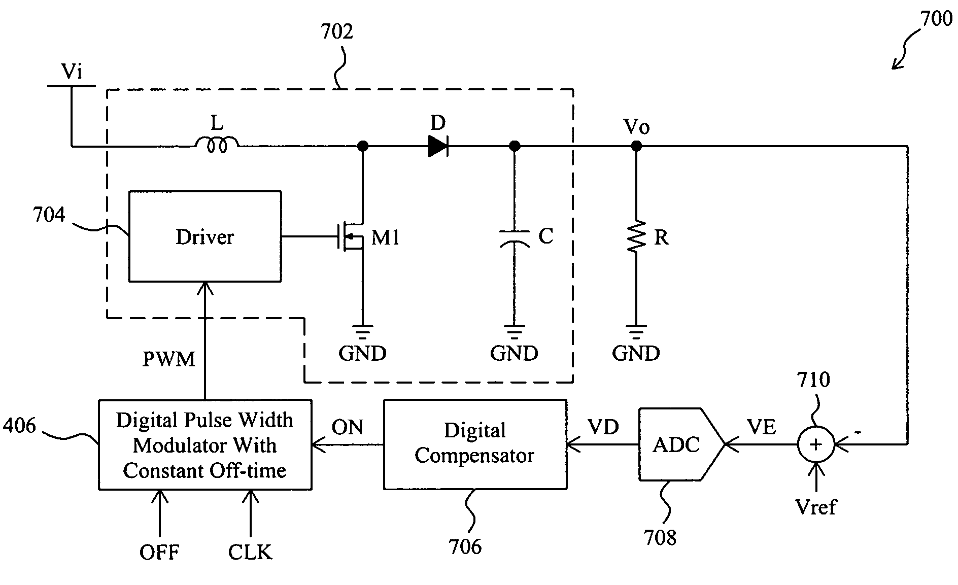
[0021]FIG. 4 shows a buck-boost converter 400 according to the present invention, in which an output stage 402 is used to convert an input voltage Vi to an output voltage Vo, an error amplifier 412 subtracts the output voltage Vo from a reference voltage Vref to generate an error signal VE, then an analog to digital converter 410 quantifies the error signal VE to produce a digital error signal VD, a digital compensator 408 determines an on-time period ON based on the digital error signal VD, and a digital pulse width modulator 406 generates a pulse width modulation signal PWM based on the on-time period ON, a predetermined off-time period OFF, and a clock CLK for a driver 404 in the output stage 402 to switch a switch M1. The on-time period ON determines the on-time Ton of the pulse width modulation signal PWM, and the off-time period OFF is a constant value and determines the off-time Toff of the pulse width modulation signal PWM. From the equations EQ-1 and EQ-3, it is obtained th...


PUM


Abstract

In a digital boost or buck-boost converter, a pulse width modulation signal has an on-time and an off-time. A constant off-time period is provided to set the off-time to be constant, and an on-time period to determine the on-time is derived by monitoring the output voltage of the converter. With the constant off-time, the output voltage and the on-time period will have a linear relation, thereby reducing the output ripple when the converter operates with a high duty-ratio.

Description

FIELD OF THE INVENTION[0001]The present invention is related generally to a digital voltage converter and, more particularly, to a digital voltage converter with constant off-time.BACKGROUND OF THE INVENTION[0002]Due to the advantages of small size, reduced number of passive elements and lower cost, digital voltage converters have been popularly adopted. FIG. 1 shows a conventional digital boost converter 100, in which an output stage 102 converts an input voltage Vi to an output voltage Vo, an error amplifier 112 generates an error signal VE based on the output voltage Vo and a reference voltage Vref, an analog to digital converter 110 quantifies the error signal VE to generate a digital error signal VD, a digital compensator 108 generates a duty-ratio d by compensating the digital error signal VD, and a digital pulse width modulator 106 generates a pulse width modulation signal PWM based on the duty-ratio d for a driver 104 in the output stage 102 to switch a power switch M1. The ...

Claims


Application Information

Patent Timeline
Patent Type & Authority Patents(United States)
IPC IPC(8): G05F1/00G05F1/613
CPCH02M3/157H02M3/1582
Inventor CHANG, WEI-HSU
Owner RICHTEK TECH
Why Eureka
Try Eureka