Registration of human anatomy integrated for electromagnetic localization
Active Publication Date: 2010-02-02
MEDTRONIC NAVIGATION
View PDF613 Cites 108 Cited by
Summary
Abstract
Description
Claims
Application Information
AI Technical Summary
This helps you quickly interpret patents by identifying the three key elements:
Problems solved by technology
Method used
Benefits of technology
[0015]To enhance the prior art, and in accordance with the purposes of the invention, as embodied and broadly described herein, there is provided a system for displaying relative positions of two structures during a procedure on a body. The system comprises memory for storing an image data set representing the position of the body based on scans of the body, the image data set having a plurality of data points in known relation to a plurality of reference points for the body; a magnetic field generator for generating a magnetic field to be sensed by one or more magnetic field sensors placed in
Problems solved by technology
Third, repeat fixation devices entail the user repeatedly removing and replacing a device in known relation to the fiducial markers.
Such registration methods have additional steps during the procedure, and therefore increase the complexity of the system and increase opportunities for introduction of human error.
Inaccuracies in defining the target position can create inaccuracies in placing a thera
Method used
Image
Click on the blue label to locate the original text in one second.
Reading with bidirectional positioning of images and text.
Examples
Embodiment Construction
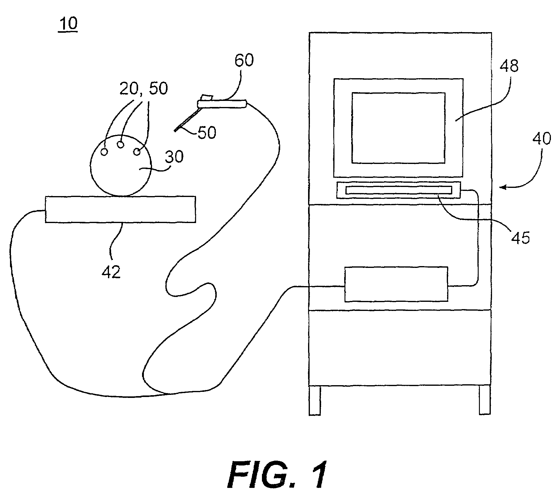
[0036]Reference will now be made in detail to the present preferred exemplary embodiments of the invention, examples of which are illustrated in the accompanying drawings. Wherever possible, the same reference numbers will be used throughout the drawings to refer to the same or like parts.
[0037]In accordance with the present invention, a method for use during a procedure on a body generates a display representing relative positions of two structures during the procedure. The method comprises the steps of (i) storing an image data set in memory, the image data set representing the position of the body based on scans taken of the body prior to the procedure; (ii) reading the image data set stored in the memory, the image data set having a plurality of data points in known relation to a plurality of reference points for at least one of the two structures; (iii) placing one or more magnetic field sensors in known relation to the reference points of the two structures; (iv) generating a ...
PUM
Abstract
A method for use during a procedure on a body. The method generates a display representing relative positions of two structures during the procedure. The method comprises the steps of storing an image data set in memory, the image data set representing the position of the body based on scans taken of the body prior to the procedure; reading the image data set stored in the memory, the image data set having a plurality of data points in known relation to a plurality of reference points for at least one of the two structures; placing one or more magnetic field sensors in known relation to the reference points of the two structures; generating a magnetic field; detecting the magnetic field with the magnetic field sensors; ascertaining the locations of the sensors based upon the magnetic field detected by the sensors and processing the locations of the sensors to generate a displaced image data set representing the relative position of the two structures during the procedure; and generating a display based on the displaced image data set illustrating the relative position of the two structures during the procedure.
Description
RELATED APPLICATIONS[0001]The following United States patent applications, were filed on Oct. 28, 1999, and are fully incorporated herein by reference: Method and System for Navigating a Catheter Probe in the Presence of Field-influencing Objects, by Michael Martinelli, Paul Kessman and Brad Jascob, assigned U.S. patent application Ser. No. 60 / 161,991; Patient-shielding and Coil System, by Michael Martinelli, Paul Kessman and Brad Jascob, assigned U.S. patent application Ser. No. 60 / 161,889; Navigation Information Overlay onto Ultrasound Imagery, by Paul Kessman, Troy Holsing and Jason Trobaugh, assigned U.S. patent application Ser. No. 09 / 428,720 (now U.S. Pat. No. 6,379,302); Coil Structures and Methods for Generating Magnetic Fields, by Brad Jascob, Paul Kessman and Michael Martinelli, assigned U.S. patent application Ser. No. 60 / 161,990; Registration of Human Anatomy Integrated for Electromagnetic Localization, by Mark W. Hunter and Paul Kessman, assigned U.S. patent application...
Claims
Application Information
Patent Timeline
Application Date:The date an application was filed.
Publication Date:The date a patent or application was officially published.
First Publication Date:The earliest publication date of a patent with the same application number.
Issue Date:Publication date of the patent grant document.
PCT Entry Date:The Entry date of PCT National Phase.
Estimated Expiry Date:The statutory expiry date of a patent right according to the Patent Law, and it is the longest term of protection that the patent right can achieve without the termination of the patent right due to other reasons(Term extension factor has been taken into account ).
Invalid Date:Actual expiry date is based on effective date or publication date of legal transaction data of invalid patent.