
Tire for two-wheeled vehicle comprising looped crown reinforcement

a two-wheeled vehicle and reinforcement technology, applied in the field of tires, can solve the problems of reducing the effectiveness of the reinforcement elements in this zone, large curvature values, and the traditional characteristics of the tires described in this document, and achieve the effect of improving the quality of motorcycle tires

Inactive Publication Date: 2010-02-09
MICHELIN RECH & TECH SA
View PDF21 Cites 12 Cited by
  • Summary
  • Abstract
  • Description
  • Claims
  • Application Information

AI Technical Summary

Benefits of technology

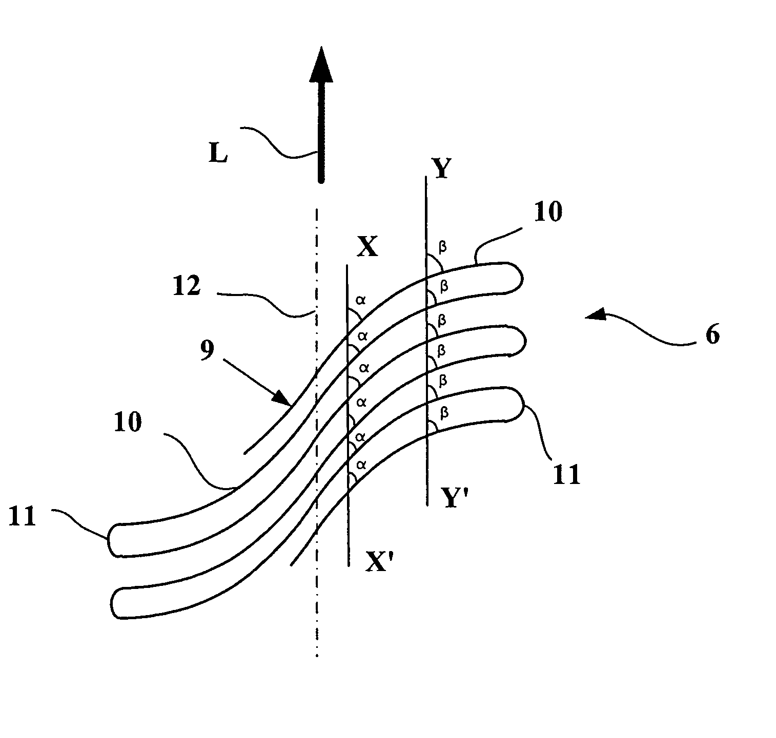
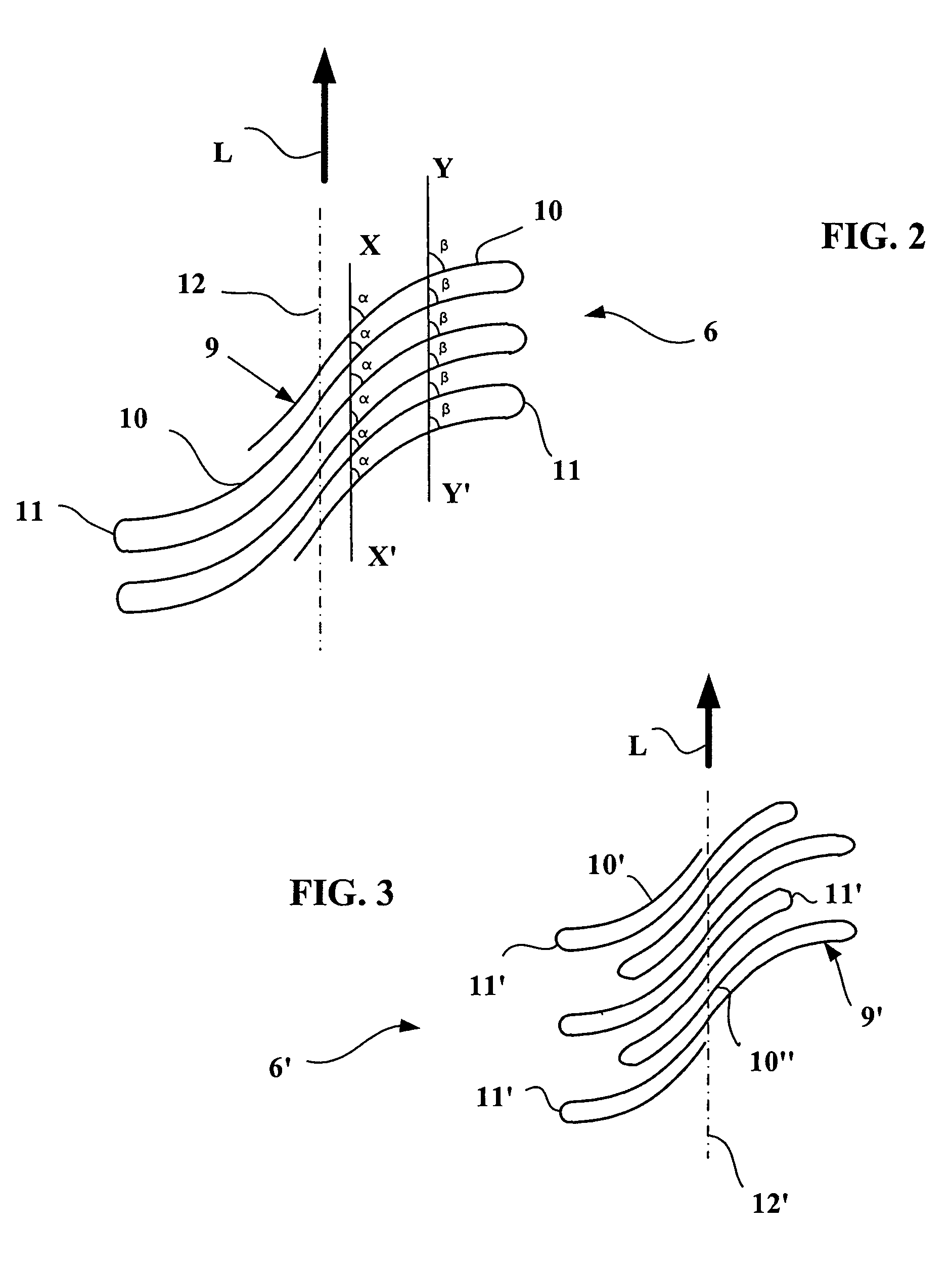
[0033]Use of a method of the hard core type which in particular allows positioning of the reinforcement elements in the quasi-final position without the need for a shaping stage exhibits further advantages. In fact, a method of the hard core type in particular allows simple angle variations distinctly greater than it is possible to obtain using processes comprising a shaping stage. Furthermore, said angle variations, said angle tending towards 90° at the edges of the working layers, result in an increase in pitch and promote production of the loops, due to the reduction in bulk.
[0054]In an advantageous variant of the invention, a layer of circumferential reinforcement elements may be provided in several parts positioned at various radial positions or different levels of the tire. Such a tire may in particular comprise a part of the layer of circumferential reinforcement elements radially to the outside of the other reinforcement elements in the central part of the tire, that is to say under the central part of the tread. This part of the layer of circumferential reinforcement elements thus allows in particular protection of the carcass against any stresses which may affect the central part of the tread, considered as the most exposed. Lateral parts of the layer of circumferential reinforcement elements, independent of the central part of said layer of circumferential reinforcement elements, may be positioned at any level, that is to say either radially to the inside of the working layers or between them or indeed radially to the inside of the carcass layer, in particular with a view to reducing the quantity of reinforcement elements and the time required to produce such a layer of circumferential reinforcement elements. The invention additionally provides, in the case of a layer of circumferential reinforcement elements made in several parts positioned in different radial positions, for the distribution of these various parts not to be symmetrical relative to the equatorial plane, or circumferential plane passing through the centre of the crown of the tire. Such an asymmetrical distribution may additionally be associated with the selection of different materials from the circumferential reinforcement elements, as mentioned above.

Problems solved by technology

Furthermore, the tires described in this document do not have the “traditional”carcass ply turn-up about a bead wire.
The production of motorcycle tires results in large curvature values if such tires are to be used on a camber.
A local tension of zero for the reinforcement elements results in reduced effectiveness of said reinforcement elements in this zone.

Method used


Image

  • Tire for two-wheeled vehicle comprising looped crown reinforcement
  • Tire for two-wheeled vehicle comprising looped crown reinforcement
  • Tire for two-wheeled vehicle comprising looped crown reinforcement

Examples


Embodiment Construction

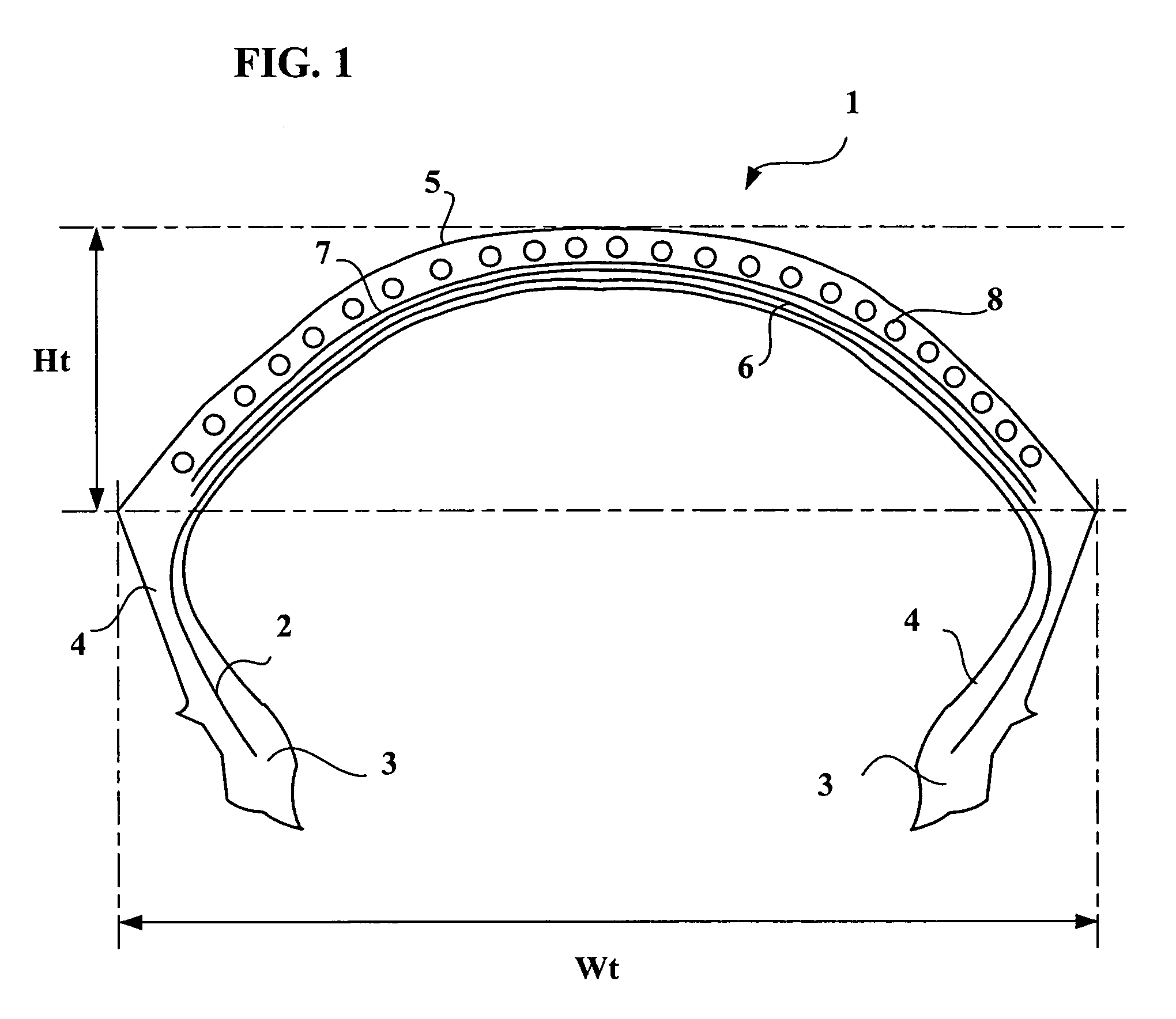
[0063]To simplify understanding thereof, the FIGS. 1 to 6 are not to scale.

[0064]FIG. 1 shows a tire 1 comprising a carcass reinforcement consisting of a single layer 2 comprising reinforcement elements of textile type. The layer 2 consists of reinforcement elements disposed radially. The radial positioning of the reinforcement elements is defined by the laying angle of said reinforcement elements; a radial arrangement corresponds to a laying angle of said elements relative to the longitudinal direction of the tire of between 65° and 90°.

[0065]Said carcass layer 2 is anchored on either side of the tire 1 in a bead 3 whose base is intended to be mounted on a rim seat. Each bead 3 is extended radially towards the outside by a sidewall 4, said sidewall 4 meeting up radially towards the outside with the tread 5. The tire 1 thus constituted has a value of curvature greater than 0.15 and preferably greater than 0.3. The value of curvature is defined by the Ht / Wt ratio, that is to say by t...


PUM

PropertyMeasurementUnit
anglesaaaaaaaaaa
anglesaaaaaaaaaa
angleaaaaaaaaaa

Abstract

A motorcycle tire includes at least one carcass-type reinforcement structure formed of reinforcement elements, anchored on either side of the tire to a bead whose base is intended to be mounted on a rim seat, each bead being extended radially towards the outside by a sidewall. The sidewalls meet up radially towards the outside with a tread. Under the tread there is a crown reinforcement structure including at least one layer of reinforcement elements known as a working layer which has at least one continuous reinforcement cord forming portions in the central zone thereof. Those central cord portions display identical angles of between 10-80 degrees formed with the longitudinal direction, the angles being measured at points of intersection of the cord with a circumferential plane. Two adjacent cord portions are linked by a U-shaped loop.

Description

[0001]This application is a continuation of International Application PCT / EP03 / 008708 filed on Aug. 6, 2003 and which claims priority of Patent Applications No. 02 / 10187 filed on Aug. 9, 2002 and No. 02 / 14415 filed on Nov. 18, 2002 in France.BACKGROUND OF THE INVENTION[0002]The present invention relates to a tire intended to be fitted on a vehicle and more particularly intended to be fitted on a two-wheeled vehicle such as a motorcycle.[0003]Although not limited to such an application, the invention will be more particularly described with reference to such a motorcycle, or motorbike, tire.[0004]Tire reinforcement armatures or tire reinforcements, in particular for motorcycle tires, are currently—and most frequently—formed by stacking one or more plies conventionally designated “carcass plies”, “crown plies”, etc. This way of designating reinforcement armatures stems from the manufacturing process, which consists of making a series of semi-finished products in the form of plies, pro...

Claims


Application Information

Patent Timeline
Patent Type & Authority Patents(United States)
IPC IPC(8): B60C9/22B60C9/18B60C9/20B29D30/16B29D30/38B29D30/70B60C9/26
CPCB60C9/20B60C9/22B60C9/0207B60C9/263Y10T152/10783Y10T152/10792B60C2009/2025
Inventor VALLE, ALAINPROST, PASCALGUERINON, BERNARD
Owner MICHELIN RECH & TECH SA
Learn More