
Wheel with tension spokes and a method of manufacturing such wheel

a technology of tension spokes and wheels, which is applied in the direction of spoked wheels, hubs, transportation and packaging, etc., can solve the problems of reducing affecting the service life of the wheel, so as to reduce the adjustment time

Inactive Publication Date: 2010-02-09
MAVIC SA
View PDF36 Cites 24 Cited by
  • Summary
  • Abstract
  • Description
  • Claims
  • Application Information

AI Technical Summary

Benefits of technology

"The invention is a wheel with spokes that connect the rim and hub. The spokes are distributed in two groups, one without tensioning and one with tensioning between the rim and hub. The method of manufacturing the wheel includes assembling the spokes to the rim and hub, and adjusting the tension of the spokes in the second group using a tensioning device. This method reduces the adjustment time by at least half because only one group of spokes needs adjusting."

Problems solved by technology

For a spoke made of metal, these stresses can, over time, cause cracks leading to ruptures.
Adjusting the geometry of a rim can be a time-consuming and expensive process, as it requires each spoke to be individually adjusted.
However, this significantly increases the weight and inertia of the wheel.
Moreover, the screw / nipple connection of the tensioning device creates weakened zones where the transmission of forces and the fatigue strength are not controlled as well as in the body of the spoke itself.
In the case of composite spokes, the use of a screw / nipple adjusting device, which is necessarily metallic and, therefore, sensitive to the phenomena of fatigue rupture, diminishes the fatigue strength of the spoke / adjusting device assembly and, therefore, limits the advantage of using a composite spoke.
These screw / nipple adjusting devices also constitute a weight increase, also reducing the advantage of using composite spokes.
However, once the spokes are tensioned, the geometry of the rim cannot be modified.
The fact that the wheel does not include any final adjusting mechanism may result in wasting a substantial quantity of material and in considerably increasing the production cost.
Moreover, the monolithic structure of the wheel does not allow repairs, since the wheel, along with the hub, must be entirely replaced in the case of a problem.

Method used


Image

  • Wheel with tension spokes and a method of manufacturing such wheel
  • Wheel with tension spokes and a method of manufacturing such wheel
  • Wheel with tension spokes and a method of manufacturing such wheel

Examples


Embodiment Construction

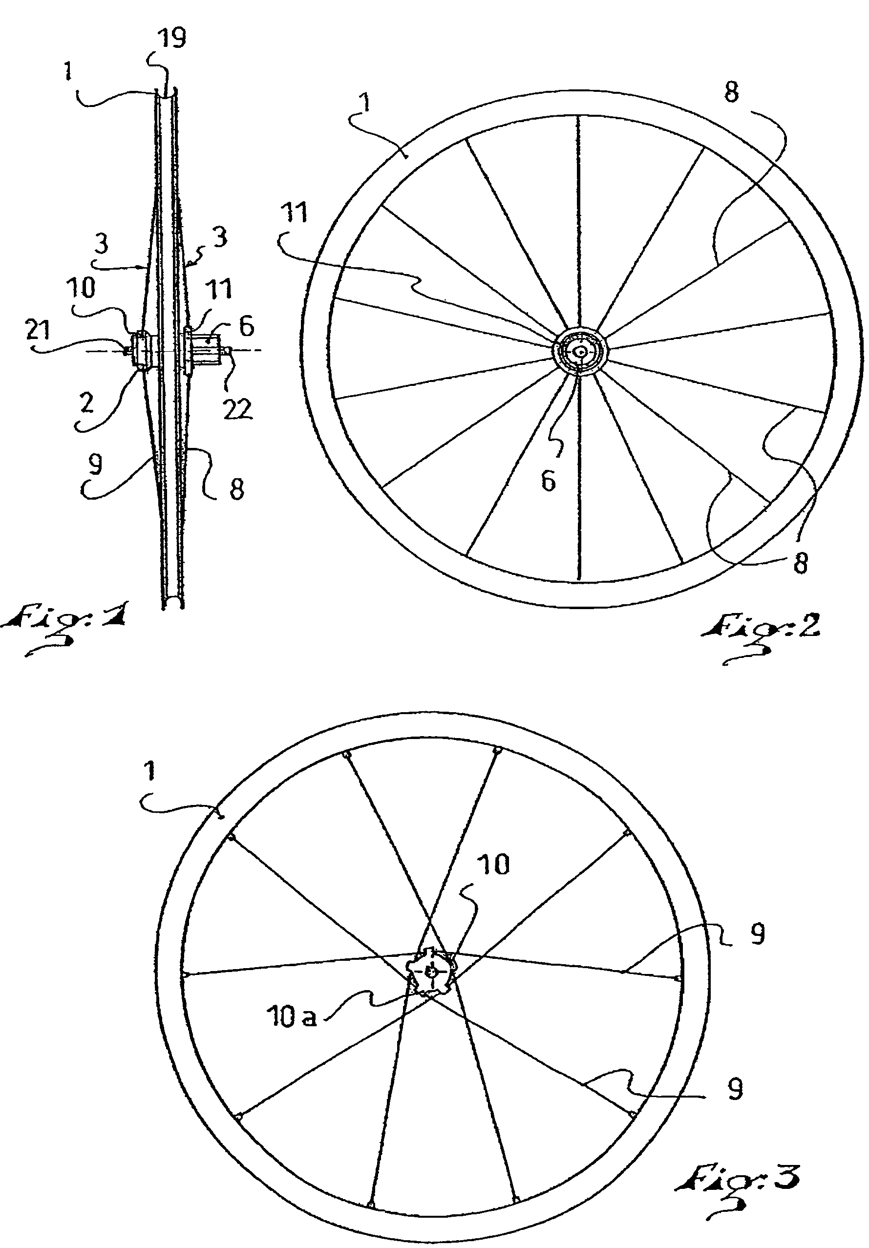
[0039]FIG. 1 shows a wheel having a peripheral rim 1, a central hub 2 and spokes 3 extending between the rim and the hub 2. The rim 1 is of a known type and has any appropriate symmetrical or non-symmetrical cross-sectional profile. However, a particular cross-sectional profile is described below in connection with FIGS. 5 and 7. Conventionally, the exterior of the rim has a channel 19 for receiving a tubular or a pneumatic tire. The interior of the rim is provided with spoke fastening devices that are of any appropriate type, and two particular embodiments of which are described below in connection with FIGS. 5, 7 and FIGS. 8 to 11.

[0040]The hub 2 can be of any appropriate type. According to the embodiment shown, the wheel is a rear wheel and the hub 2 has, on one side, a free wheel body 6 that is provided to receive transmission gear wheels. It has ends 21, 22 for attachment to the bicycle frame.

[0041]The fact that the wheel is a rear wheel is not limiting; the invention also appl...


PUM

PropertyMeasurementUnit
densityaaaaaaaaaa
densityaaaaaaaaaa
distanceaaaaaaaaaa

Abstract

A wheel including a peripheral rim, a central hub, and spokes connecting extending and tensioned between the rim and the hub, as well as a method for manufacturing such a wheel. The method includes distributing the spokes in two groups, a first group of spokes lacking a tensioning device, and a second group of spokes having a tensioning device; assembling the spokes to the rim and to the hub, and then adjusting the tension of the spokes with tensioning devices of the second group of spokes.

Description

CROSS-REFERENCE TO RELATED APPLICATION[0001]This application claims priority under 35 U.S.C. §119 of French Patent Application No. 05.09501, filed on Sep. 16, 2005, and French Patent Application No. 05.13086, filed on Dec. 21, 2005, the disclosures of which applications are hereby incorporated by reference thereto in their entireties.BACKGROUND OF THE INVENTION[0002]1. Field of the Invention[0003]The invention relates to a bicycle wheel having tension spokes and to a method for manufacturing such a wheel. More particularly, in a non-limiting embodiment, the rim and spokes of the wheel are made from a composite material.[0004]2. Description of Background and Relevant Information[0005]As is known, a wheel with tension spokes includes a peripheral rim having a channel for receiving a tire, typically a pneumatic tire, as well as a central hub and spokes extending between the rim and the hub.[0006]Spokes are usually distributed in two sets, the spokes of each set connecting the rim to re...

Claims


Application Information

Patent Timeline
Patent Type & Authority Patents(United States)
IPC IPC(8): B60B1/04
CPCB60B1/0207B60B1/0215B60B1/0261B60B1/0276B60B1/041B60B1/044B60B5/02B60B21/023B60B21/025B60B21/062B60B1/042Y10T29/49506
Inventor MERCAT, JEAN-PIERREAUGRIS, FABRICE
Owner MAVIC SA
Learn More