Backlight module

a backlight module and led technology, applied in the field of backlight modules, can solve the problems of increased price, increased complexity of backlight modules incorporating leds, and no longer satisfying the needs of customers, and achieve the effect of improving color saturation

Active Publication Date: 2010-02-09
AU OPTRONICS CORP
View PDF11 Cites 16 Cited by
  • Summary
  • Abstract
  • Description
  • Claims
  • Application Information

AI Technical Summary

Benefits of technology

[0010]The backlight module, according to the present invention, comprises a light guide plate; a light source positioned at a side of the light guide plate; a diffuser sheet positioned on the light guide plate; and a mixing space positioned between the light guide plate and the diffuser sheet. The light guide plate comprises a light-exit face and at least a light-incidence face. The light emitting from the light source enters the light guide plate from the light-incidence face. The diffuser sheet does not contact the light guide plate and the light source. In addition, the mixing space is positioned between the light guide plate and the diffuser sheet, so the light passing through the light-exit face can be mixed sufficiently in the light mixing space before going out from the backlight module.
[0011]The backlight module of the present invention comprises a light guide plate and the light source is positioned at a side of the light guide plate, so the light can be distributed properly through the light guide plate. Furthermore, the backlight module in the present invention further comprises a light mixing space positioned between the light guide plate and the diffuser sheet to make the light mix sufficiently in the light mixing space before going out from the backlight module so the white light with better color saturation can be formed.

Problems solved by technology

However, the large size of the CCFL and the high illuminating heat become restrictions of LCDs, so the CCFL no longer satisfy the customers' demands.
In addition, the CCFL contains mercury, which causes environment pollution.
Therefore, the backlight module incorporating LEDs has a more complicate structure and higher price than the backlight module incorporating the CCFL.
However, the increased number of LED sources 14 increases the cost of the backlight module 10.
In addition, according to the structural design of the backlight module 10, the light cannot mix well.
However, this design increases the thickness of the backlight module, and fans, heat pipes, or other heat dissipation devices are needed to help heat dissipation, so the cost is increased.
In addition, special design prisms are usually patented, so the product cost of the backlight module is also increased.

Method used


Image

  • Backlight module
  • Backlight module
  • Backlight module

Examples


first embodiment

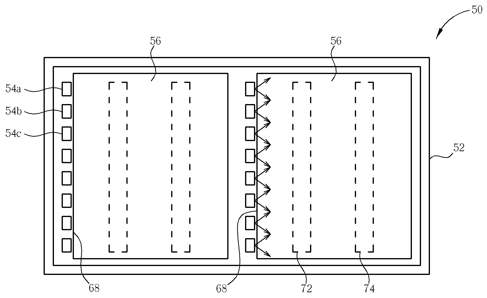
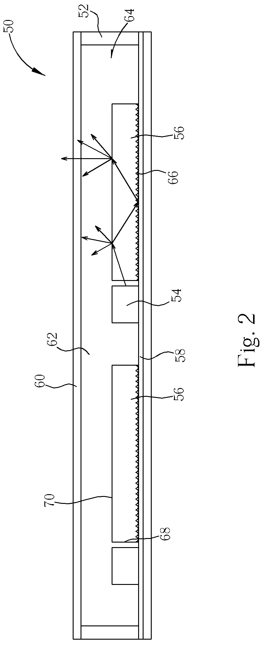
[0019]The backlight module of the present invention can be applied to LCDs or other display devices, which require a light source. FIG. 2 depicts a side view of the backlight module in present invention while FIG. 3 depicts a top view of the backlight module in FIG. 2. The backlight module 50 in the present invention is direct-lighting type, and can be applied to small-, medium-, and large-size LCDS. The backlight module 50 comprises a frame 52, a plurality of light guide plates 56 positioned in parallel at the bottom of the backlight module 50, a light sources 54, a diffuser sheet 60, and a light mixing space 62. The frame 52 comprises at least four sidewalls forming a containing space 64 to hold the light source 54, the light guide plate 56, and the diffuser sheet 60.

[0020]Every light guide plate 56 comprises a light-incidence face 68 and a light-exit face 70 connected to each other perpendicularly, and the surface of each light guide plate 56 comprises a plurality of light guide ...

second embodiment

[0026]FIG. 4 shows a schematic diagram of the backlight module in the present invention. In FIG. 4, the same number numerals as FIG. 3 designate similar or the same parts, regions or elements. In this embodiment, the light source 54 is a double-emitting light source, and positioned between two adjacent light guide plates 56. The light-incidence face 68 is positioned on two sides of the light source 54 to guide the light emitted from the light source 54 to enter the light guide plate 56 from the light-incidence face 68 of the light guide plate 56. The advantage of the present invention is that by using the double-emitting light source, the number of light sources can be decreased, and heat dissipation ability is increased. Furthermore, the space of the device is spared and the electricity consumption is reduced.

[0027]In other embodiments, a light guide plate 56 can comprise two light-incidence faces 68 at the same time, and a light source 54 can be positioned at two sides of the ligh...

third embodiment

[0028]FIG. 5 shows a schematic diagram of the backlight module in the present invention. The backlight module 100 comprises a frame 102 forming a containing space 114, at least two light guide plates 106, a light source 104 positioned at a side of the light guide plates 106, a reflective sheet 108 positioned under the light source 104 and the light guide plates 106, a diffuser sheet 110 positioned on the light source 104 and the light guide plates 106, and a light mixing space 112 surrounded by the diffuser sheet 110, the light source 104 and the light guide plates 106. The preferred light source in the present invention is a point light source, and a better light source is a top-emitting LED positioned on a PCB. Therefore, the light guide plates 106 are a little higher than the light source 104, and the light-incidence face 118 is positioned at a side of the light guide plates 106, which is parallel to the light-exit face 120. Thus, the light emitted from the top of the light sourc...


PUM


Abstract

A backlight module includes a light guide plate, a light source disposed at a side of the light guide plate, a diffuser sheet positioned over the light guide plate but not directly contacting the light guide plate, and a light mixing space positioned between the light guide plate and the diffuser sheet so that light emitted from the light guide plate efficiently mixes in the light mixing space before entering the diffuser sheet and emitted out of the backlight module.

Description

BACKGROUND OF THE INVENTION[0001]1. Field of the Invention[0002]The present invention relates to a backlight module, and more particularly to a backlight module comprising a light mixing space positioned between a light guide plate and a diffuser sheet.[0003]2. Description of the Prior Art[0004]As quality demands increase rapidly for display devices, LCDs are becoming a major type of display devices today, finding wide application to notebooks, personal digital assistants, digital cameras and other portable electronic products. Because the LCD is a passive illuminating display device, a backlight module is often necessary to provide a light source for it.[0005]A conventional backlight module of the LCD uses a cold cathode fluorescent lamp (CCFL) as the light source. Taking a direct-lighting type backlight module as an example, a plurality of CCFLs are positioned collaterally on the bottom of the backlight module to provide a plurality of line-like sources. A diffuser sheet, or a plu...

Claims


Application Information

Patent Timeline
Patent Type & Authority Patents(United States)
IPC IPC(8): F21V7/04
CPCG02B6/0078G02B6/0051G02B6/0018G02B6/0021G02B6/0035
Inventor LIU, PANG-HSUAN
Owner AU OPTRONICS CORP
Why Eureka
Try Eureka