
Rotation brake method and device for working machine

a technology of rotating brake and working machine, which is applied in the direction of motor/generator/converter stopper, dynamo-electric converter control, instruments, etc., can solve the problems of poor practicality in installation space and cost, difficult to stop the revolving, and high cost, so as to prevent the damage of the mechanical brake

Inactive Publication Date: 2010-02-09
KOBELCO CONSTR MASCH CO LTD +1
View PDF12 Cites 13 Cited by
  • Summary
  • Abstract
  • Description
  • Claims
  • Application Information

AI Technical Summary

Benefits of technology

This approach allows for rapid deceleration and stopping of the revolving superstructure in emergencies while preventing mechanical brake damage, maintaining practicality in terms of size and cost by leveraging the electric motor's regenerative braking and controlled mechanical brake activation.

Problems solved by technology

In the event of a malfunction such that power supply to the swiveling electric motor is interrupted due to a failure of a power generator, etc., or the swiveling electric motor becomes out of control due to a failure in a swivel control system, the above conventional technique will involve a situation where only inertia of the revolving superstructure acts on the electric motor as with a neutral free mode in a hydraulic motor-based system, without any braking based on the power generating action of the electric motor, and it will take time to stop the revolving superstructure.
However, the mechanical brake originally has only a brake performance designed for a stop-holding brake.
Therefore, if the mechanical brake is activated during a high-speed rotation, it is likely to be damaged due to lack of its own heat capacity.
That results in poor practicality in terms of installation space and cost.

Method used


Image

  • Rotation brake method and device for working machine
  • Rotation brake method and device for working machine
  • Rotation brake method and device for working machine

Examples


Embodiment Construction

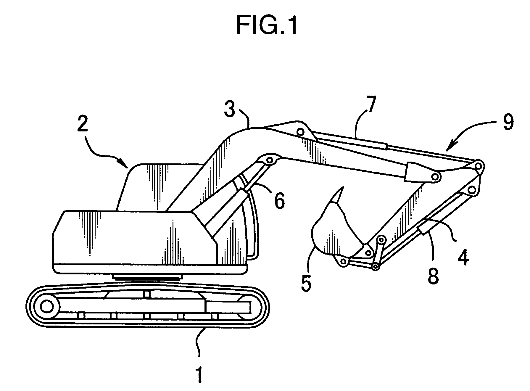
[0019]FIG. 1 shows an excavator as one object intended to apply the present invention thereto.

[0020]This excavator comprises a crawler undercarriage 1, and a revolving superstructure 2 mounted on the crawler undercarriage 1 rotatably about a vertical axis. The revolving superstructure 2 is provided with a plurality of work (excavation) attachments which include a boom 3, an arm 4, a bucket 5, and boom, arm and bucket hydraulic cylinders 6, 7, 8 for driving the boom, the arm and the bucket, respectively.

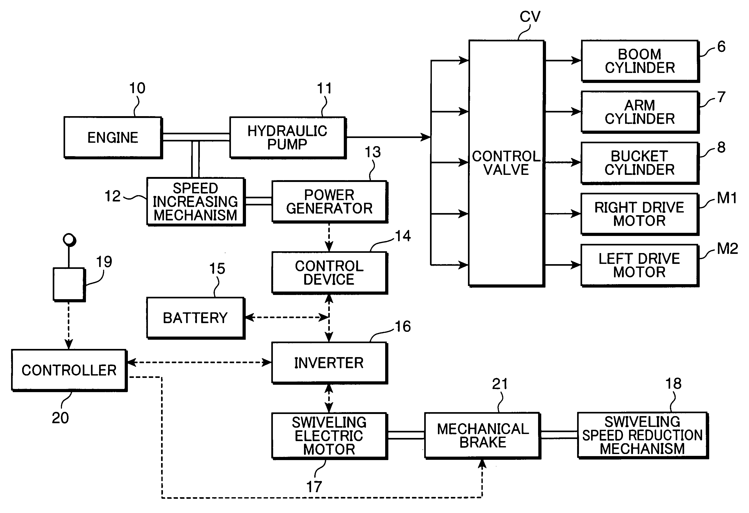
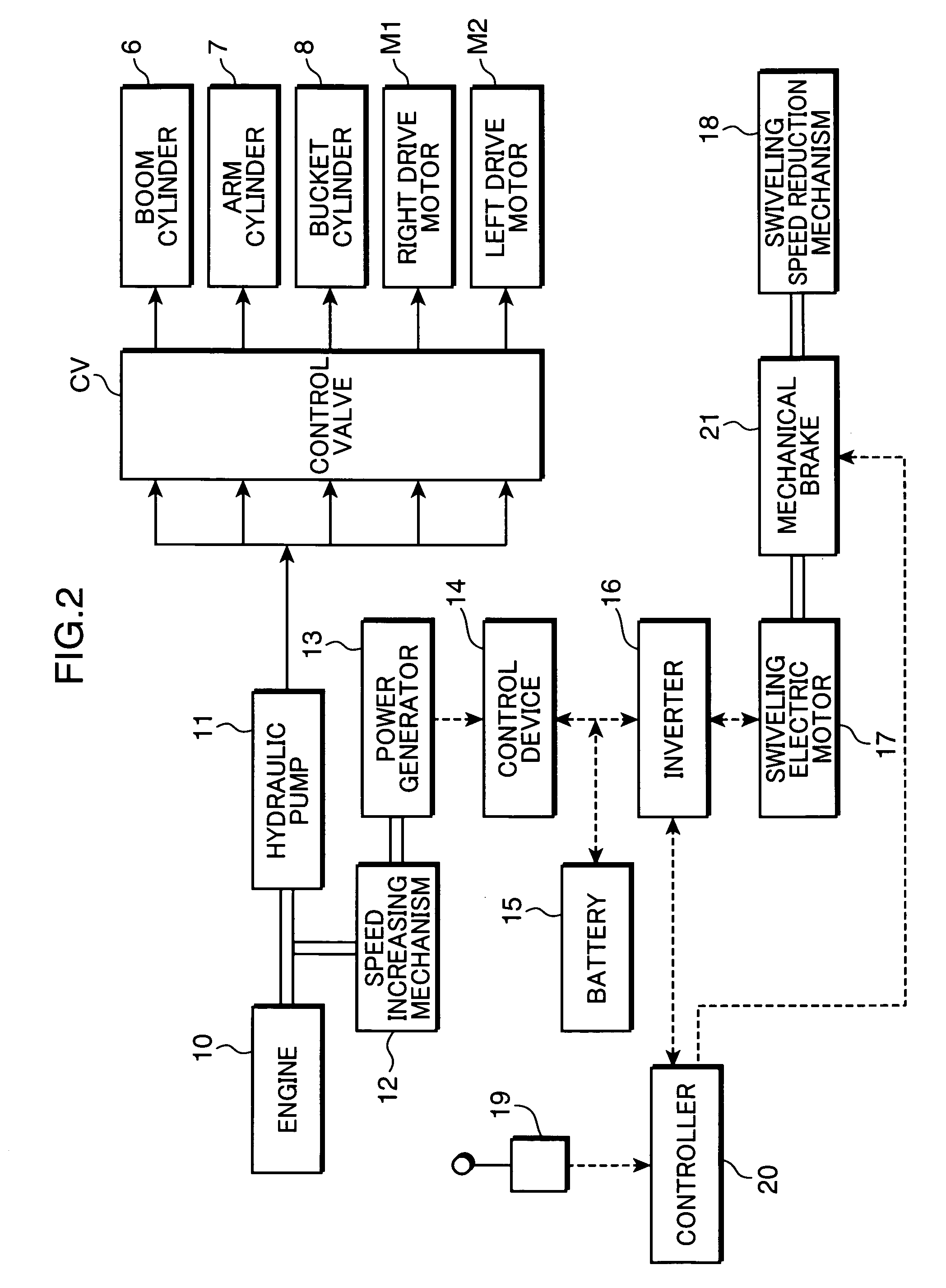
[0021]FIG. 2 shows a block diagram of a drive / control system for the entire excavator. As shown in FIG. 2, there is driven a hydraulic pump 11 by an engine 10, and a discharge oil from the hydraulic pump 11 is supplied to each of the hydraulic cylinders 6 to 8 and a pair of right and left drive motors M1, M2 for drivingly traveling the undercarriage 1, through a control valve CV (while a plurality of control valves are actually provided on an actuator-by-actuator basis, they are illus...


PUM


Abstract

To stop, in an emergency, a revolving superstructure quickly from rotating while preventing damage of a mechanical brake. A revolving superstructure is driven swiveling using a permanent magnetic-type swiveling electric motor; in an emergency, such as a malfunction in a drive or control system for the swiveling electric motor, allowing electric power generated in the electric motor due to inertial rotation to be consumed in an external braking resistor so as to make an electric braking action; and a mechanical brake is activated to stop the rotation and hold the stopped revolving superstructure when a rotation speed of the revolving superstructure becomes equal to or lower than a preset value.

Description

TECHNICAL FIELD[0001]The present invention relates to a work machine designed to drivingly swivel a revolving superstructure using an electric motor, and more specifically to a method and a system for braking the revolving superstructure in an emergency caused by interruption in power supply to a drive system for the swiveling electric motor, failure in a control system for the swiveling electric motor, etc.BACKGROUND ART[0002]For swivel-type work machines, such as an excavator or a crane, there has been known a technique of employing an electric motor as a swivel driving source, in place of a traditional hydraulic motor, as disclosed in the following Patent Publication 1.[0003]This conventional technique uses the electric motor also as a power generator to brake / stop a revolving superstructure by a regenerative braking torque from the power generating action.[0004][Patent Publication 1] Japanese Patent Laid-Open Publication No. 2001-207478[0005]In the event of a malfunction such th...

Claims


Application Information

Patent Timeline
Patent Type & Authority Patents(United States)
IPC IPC(8): H02P3/00H02K17/32H02K7/10E02F9/22B66C23/94E02F9/20E02F9/24
CPCE02F9/121E02F9/128B60L7/02B60L1/20B60L3/0076E02F9/24
Inventor YOSHIMATSU, HIDEAKIKOMIYAMA, MASAYUKISUGANO, NAOKIINOUE, KOJI
Owner KOBELCO CONSTR MASCH CO LTD
Learn More