
System and method for controlled dosing and dispensing of liquid material

a liquid material and control system technology, applied in the direction of liquid transferring devices, pliable tubular containers, transportation and packaging, etc., can solve the problems of difficult to follow the instruction to a use based on flow rate, the application rate is often difficult to calculate and difficult to understand depending on the application rate,

Inactive Publication Date: 2010-02-16
MACLEAN BLEVINS MARK T
View PDF5 Cites 34 Cited by
  • Summary
  • Abstract
  • Description
  • Claims
  • Application Information

AI Technical Summary

Benefits of technology

[0012]It is a primary object of the present invention to provide an apparatus, system and method for controlled dosing and dispensing of a liquid material which enables the end-user to achieve the correct rate of application.
[0013]It is another object of the present invention to provide an apparatus, system and method which provides an intuitive visual feedback feature to impart application rate information to the end-user as the liquid material is being dispensed.
[0014]It is another object of the present invention to provide a system and method for controlled dosing and dispensing of the liquid material which can be used by a user without measuring the liquid material, thereby protecting the user from coming into physical contact with the concentrated liquid material.
[0015]It is yet another object of the present invention to provide an apparatus to support the system and method that can be produced in a cost effective manner and that will be durable enough to satisfy the dosing and dispensing requirements for dispensing the entire contents of the affixed source container.
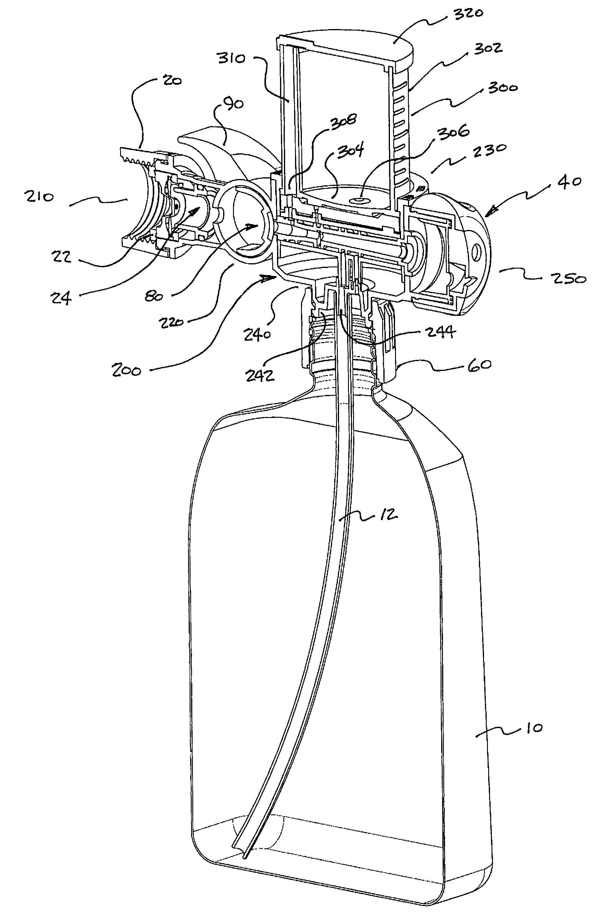
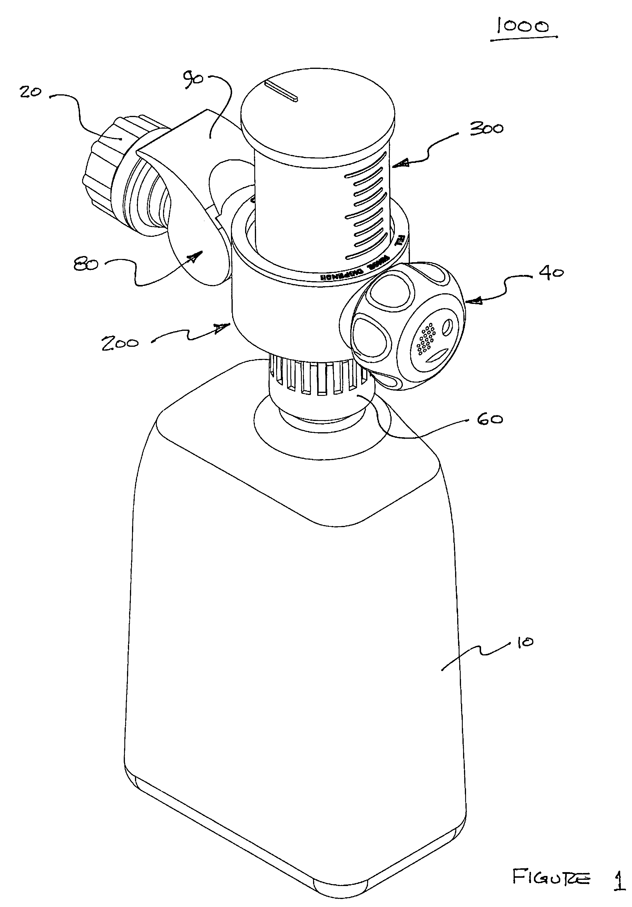
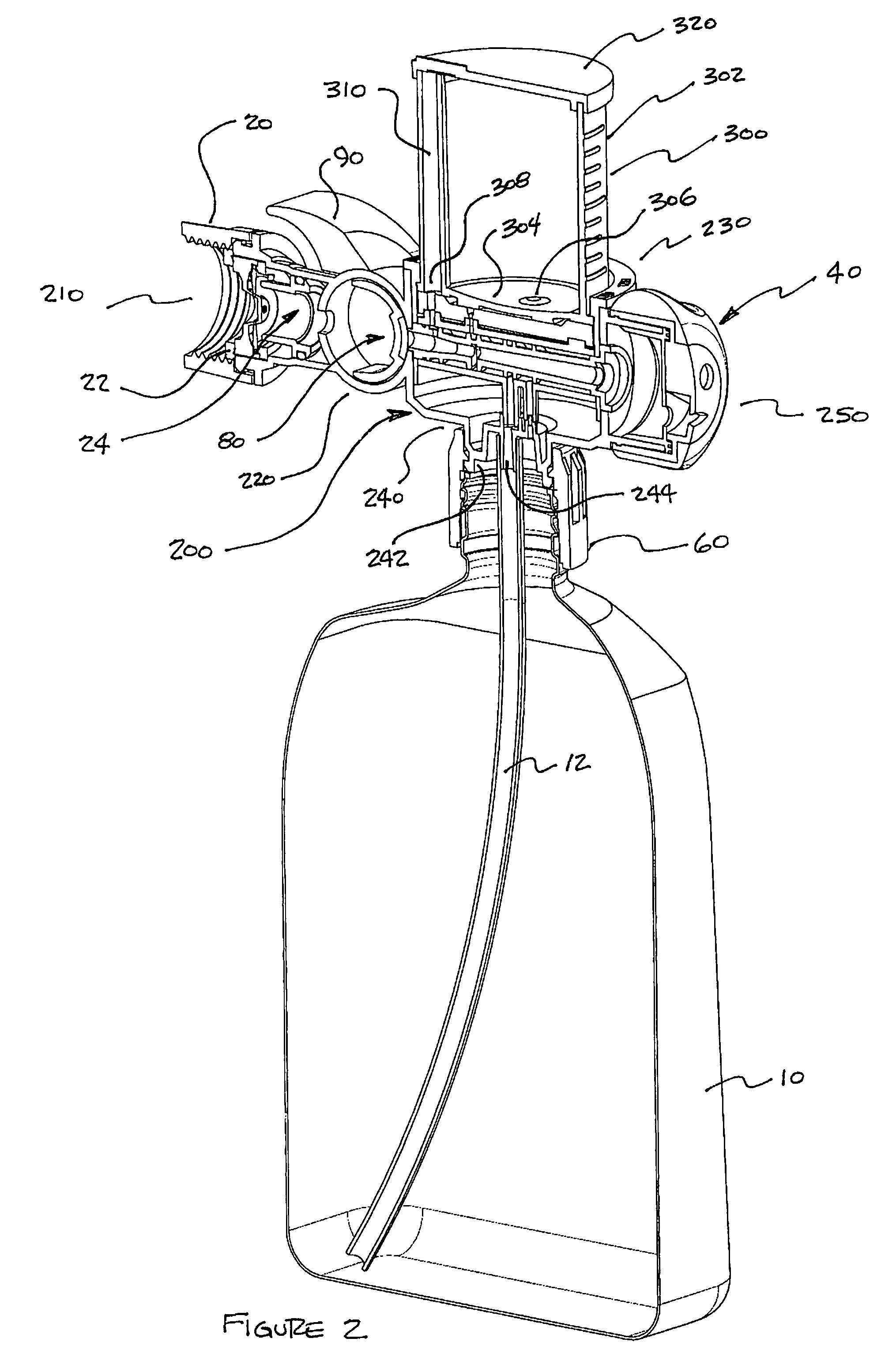
[0017]In accordance with one aspect of the present invention, various embodiments incorporate a method for selectively and accurately dosing and dispensing a predetermined liquid material which generally comprises among its combination of steps that of establishing a first source containing the predetermined liquid material and establishing a second source of a pressurized fluid stream. The method also includes the steps of attaching a housing to the first and second sources for receiving the pressurized fluid stream and controlling said pressurized fluid stream with said flow control valve means. The housing defines an admission port for selectively admitting the predetermined liquid material therethrough, as well as a flow path for the pressurized fluid stream and the sight glass style containment vessel. The method further includes the step of selectively operating a function selection valve assembly disposed in the housing's flow path, the function selection valve assembly being selectively operated to choose one of a plurality of selectable four possible functions, such as: clean, rinse, fill and dispense. When the pressurized fluid stream is directed into the flow path, the function selection valve assembly creates a low pressure condition and directs a portion of the pressurized fluid stream to provide means to accomplish each of the four functions. The method also includes the steps of filling the sight glass using the fill function and then dispensing from the sight glass, mixing with the fluid stream to dilute the liquid material and then to dispense the mixture onto a predetermined area of a surface to be treated. The method includes visual use of the sight glass as a feedback mechanism to the user for knowledge about the quantity of liquid material dispensed or available to be dispensed to the predetermined area of surface to be treated. Further, the method includes the use of the clean function to provide a rinse and flush operation to prepare the apparatus for storage until the next use is required.

Problems solved by technology

These are relatively simple to use, however the application rate is often difficult to calculate and harder to understand depending on the actual flow rates encountered.
Hence, any instruction to a use based on flow rates—(apply 10 gallons of diluted product to 100 square feet of lawn) is nearly impossible for the homeowner to follow.

Method used


Image

  • System and method for controlled dosing and dispensing of liquid material
  • System and method for controlled dosing and dispensing of liquid material
  • System and method for controlled dosing and dispensing of liquid material

Examples


Embodiment Construction

[0064]In overall operation, the controlled accurate dosing and dispensing system of the present invention serves to control the safe rate of application of liquid materials, which may be potentially hazardous. It safeguards against the accidental or uneducated overdosing or over application of the liquid material by operably coupling to the liquid material's source a pre-dispensing measuring sight glass container and valve assembly which is properly filled with liquid material from the source container for properly segregating just that portion of the liquid material to be dispensed from the apparatus. This pre-dispensing measuring sight “glass” container (which may or may not actually be formed of a glass material per se) and valve assembly is situated for easy viewing by the user and is suitably marked with volumetric graduations, such that the user can understand the total volume of concentrated liquid material delivered or yet to be delivered. This dosing and dispensing system i...


PUM


Abstract

A system and method are provided for selectively dosing and dispensing a predetermined liquid material in and from a pre-dispensing measuring sight glass container vessel, wherein a housing is disposed to receive a pressurized fluid stream, to provide an intermediate measurement and storage vessel for the liquid material and to provide a selectively operable valve assembly that is disposed in a flow path defined in the housing. The housing includes an inlet, an outlet, and an intermediate portion extending therebetween, which is formed with an admission port for admitting the predetermined liquid material. The valve assembly is disposed between the housing's inlet and outlet, and may be selectively operated to fill the sight glass container from the source container; or, to dispense the liquid material from the sight glass container; or, to clean the sight glass container; or, to just provide a flow of the pressurized fluid without any liquid material. At no selection or operating condition can liquid material from the source container be dispensed without first being measured into the sight glass container.

Description

RELATED APPLICATION DATA[0001]This Application is based on U.S. Provisional Application No. 60 / 782,537, filed 16 Mar. 2006.BACKGROUND OF THE INVENTION[0002]1. Field of the Invention[0003]The present invention is generally directed to the controlled dosing and accuracy in dispensing of liquid materials. More specifically, it is directed to the proper dosing and accuracy in the distribution or application rate of the liquid materials onto surfaces to be treated. The present invention is directed, moreover, to a system and method by which proper dosing and dispensing is effected in a manner that allows feedback to the user relative to the intended application rate of the liquid material.[0004]Dispensing control devices of the type used with a pressurized stream of fluid, such as water provided through a conventional garden hose, pump-up tank sprayer or other delivery means, are widely used in many applications. One example is a spray nozzle attachment for a garden hose which serves als...

Claims


Application Information

Patent Timeline
IPC IPC(8): A62C5/02
CPCB05B1/3026B05B7/2443B05B7/2478B05B12/081
Inventor MACLEAN-BLEVINS, MARK T.
Owner MACLEAN BLEVINS MARK T
Learn More