Curved guide mechanism and walk-assisting device

a technology of walking aids and guide mechanisms, which is applied in the direction of walking aids, physical therapy, and program-controlled manipulators, etc., can solve the problems of increased inertia moment of leg links, impaired smooth rocking motion of leg links, and large movement bodies. , to achieve the effect of improving durability and small pressing for

Active Publication Date: 2010-02-16
HONDA MOTOR CO LTD
View PDF6 Cites 5 Cited by
  • Summary
  • Abstract
  • Description
  • Claims
  • Application Information

AI Technical Summary

Benefits of technology

[0007]In view of the aforementioned problems, an object of the invention is to provide a curved guide mechanism adapted to be capable of making a movable body small in size and light in weight, and suppressing biting of foreign matters, and a walk-assisting device using this guide mechanism.
[0011]Meanwhile, it is also considered that an inner engagement element and an outer engagement element are provided in the same position in the longitudinal direction of the guide groove in the movable body. In this case, however, it is necessary to set the groove width of the guide groove to be greater than the total dimension of the diameter of the inner engagement element, the diameter of the outer engagement element, and a clearance required for prevention of contact between both engagement elements. As a result, the groove width of the guide groove becomes large, and thus, foreign matters, such as trousers, may be apt to enter into the guide groove, and the width of the movable body also becomes large. As a result, the movable body cannot be appreciably made small in size and light in weight. In contrast, according to the curved guide mechanism of the present invention, the inner engagement element and the outer engagement element are separated in the longitudinal direction of the guide groove. Therefore, the inner engagement element and the outer engagement element may be arranged so as to overlap each other within the groove width of the guide groove. Accordingly, it is sufficient if the groove width of the guide groove is a dimension obtained by adding, to the diameter of one engagement element of the inner engagement element and the outer engagement element, a clearance required for preventing this engagement to come into contact with a rail portion opposite to the rail portion to be inherently engaged with this engaging piece. As a result, the groove width of the guide groove can be small enough, and thus foreign matters hardly enter the guide groove, and the movable body can be made as small in size and light in weight as possible.
[0012]According to the walk-assisting device of the present invention using such a curved guide mechanism, foreign matters, such as trousers, can be effectively kept away from entering the guide groove, and being bitten into a space between each of the inner and outer engagement element, and each of the inner and outer peripheral rail portions, and the smoothness of rocking of the leg link can be secured. Additionally, since the movable body can be made small in size and light in weight as described above, the inertia moment of the leg link is reduced. This makes it possible to reduce user's sense of resistance by the inertia moment of the leg link when the user advances his / her leg forward.
[0013]Additionally, in the curved guide mechanism of the present invention, preferably, the inner engagement elements are respectively provided at one end and the other end of the guide groove of the movable body in the longitudinal direction, and at least one outer engagement element is provided between the inner engagement elements at both the ends. Here, when a moment (moment which acts so as to push in one of the inner engagement element and the outer engagement element into the guide groove and pull out the other one from the guide groove) in a direction orthogonal to the longitudinal direction of the guide groove is applied to the movable body, in order to reduce the force acting between each of the inner and outer engagement elements and each of the inner and outer peripheral rail portions, it is necessary to increase a distance in a direction orthogonal to the longitudinal direction of the guide groove between a place (inner engagement element engaging place) of the inner peripheral rail portion to be engaged with the inner engagement element, and a place (outer engagement element engaging place) of the outer peripheral rail portion to be engaged with the outer engagement element. In a case where the outer engagement elements are provided at both ends of the movable body, and at least one inner engagement element is provided between both the outer engagement elements, the position of the inner engagement element engaging place deviates further outward than the outer engagement element engaging place and the place of the same inner peripheral rail portion in the longitudinal direction of the guide groove, and the distance in a direction orthogonal to the longitudinal direction of the guide groove between the inner engagement element engaging place and the outer engagement element engaging place becomes short. In contrast, if outer engagement elements are provided between inner engagement elements provided at both ends of the movable body as described above, the position of the outer engagement element engaging place deviates further outward than the inner engagement element engaging place and the place of the same outer peripheral rail portion in the longitudinal direction of the guide groove, and the distance in a direction orthogonal to the longitudinal direction of the guide groove between the inner engagement element engaging place and the outer engagement element becomes long. Therefore, a force acting between each of the inner and outer engagement elements and each of the inner and outer peripheral rail portions can be reduced by a moment in a direction orthogonal to the longitudinal direction of the guide groove, and durability of the engagement elements as well as the rail portions can be improved.
[0014]In the walk-assisting device, when a user turns his / her leg outward, a moment in a direction orthogonal to the longitudinal direction of the guide groove is applied to the movable body. Accordingly, even in the walk-assisting device of the invention, durability can be improved by providing the inner engagement elements at one end and the other end, respectively, of the guide groove of the movable body in the longitudinal direction, and providing at least one outer engagement element between the inner engagement elements at both the ends.
[0016]Here, in a case where the inner engagement elements are respectively provided at one end and the other end of the movable body in the longitudinal direction (front-back directions), and at least one outer engagement element is provided between the inner engagement elements at both the ends, the tilt moment applied to the guide unit is received by the pressurization force between the inner engagement element at the front end of the movable body and the inner peripheral rail portion, and the pressurization force between the outer engagement element and the outer peripheral rail portion. This pressurization force becomes small such that the distance in the front-back directions between the inner engagement element at the front end of the movable body and the outer rotating body becomes long. Also, if the outer engagement element is provided in a position which is offset in a direction away from a line which connects a lower end of the leg link, and the center of curvature of the guide track, with respect to a centre position between the inner engagement elements at both ends, i.e., rearward, the above distance becomes long, and consequently the pressurization force becomes small, and durability is improved. In addition, in a case where, the movable body is arranged so as to be spaced forward apart from a line which connects the lower end of the leg link, and the center of curvature of the guide track, the outer engagement element may be provided in a position which is offset forward from the center position between inner engagement elements at both the ends.

Problems solved by technology

As a result, there is a problem such that the movable body becomes large and heavy, and the inertia moment of the leg link increases.
Additionally, foreign matters, such as trousers, unfavorably enter into a space between a side edge of the rail and an engagement element engaged therewith to be squeezed in the space, and the smoothness of rocking motion of the leg link might be impaired.

Method used


Image

  • Curved guide mechanism and walk-assisting device
  • Curved guide mechanism and walk-assisting device
  • Curved guide mechanism and walk-assisting device

Examples


Embodiment Construction

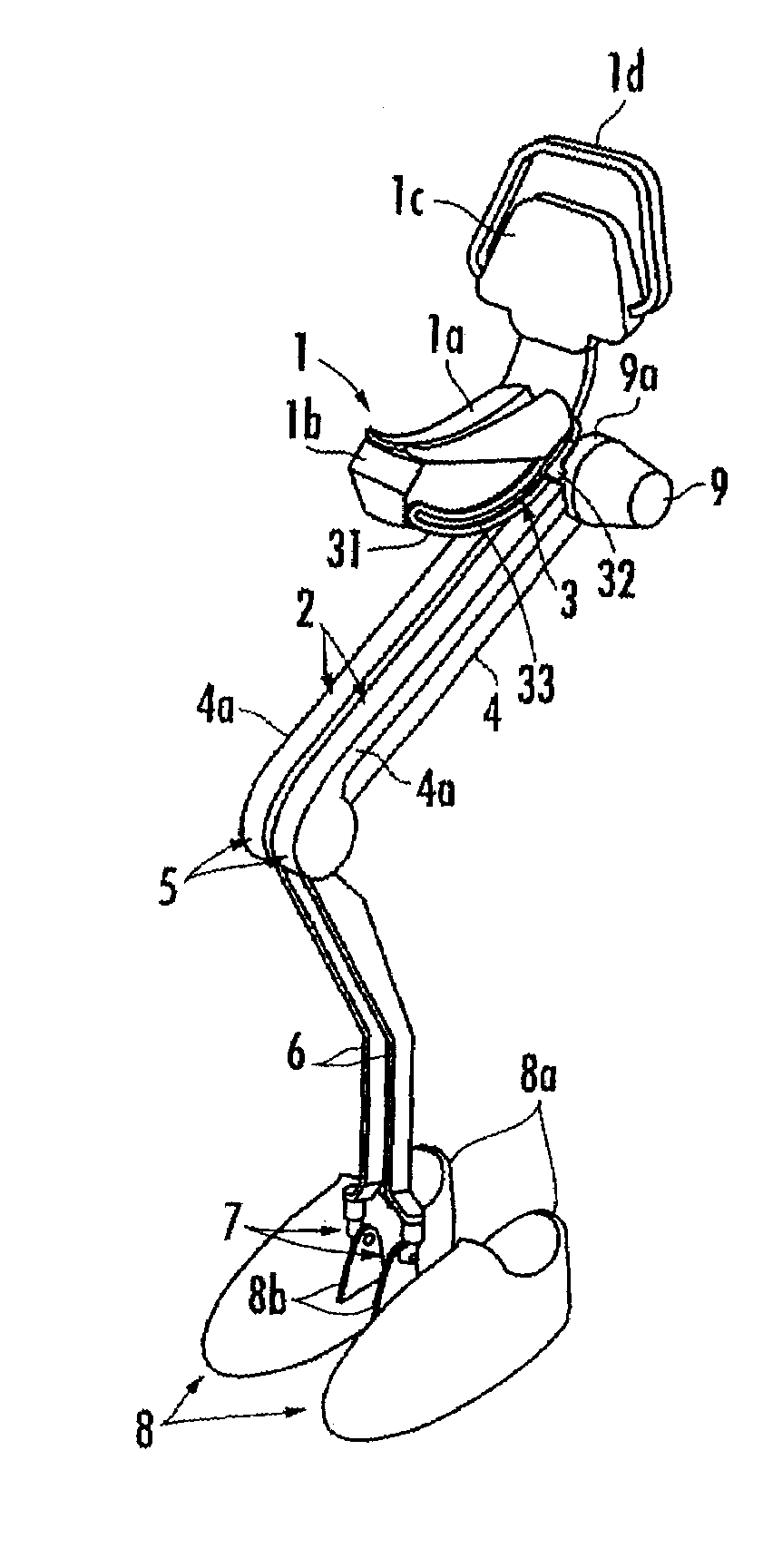
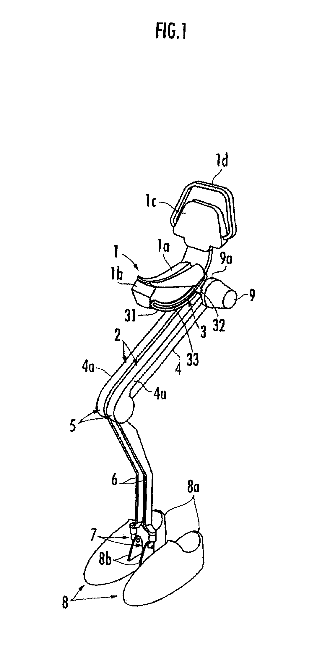
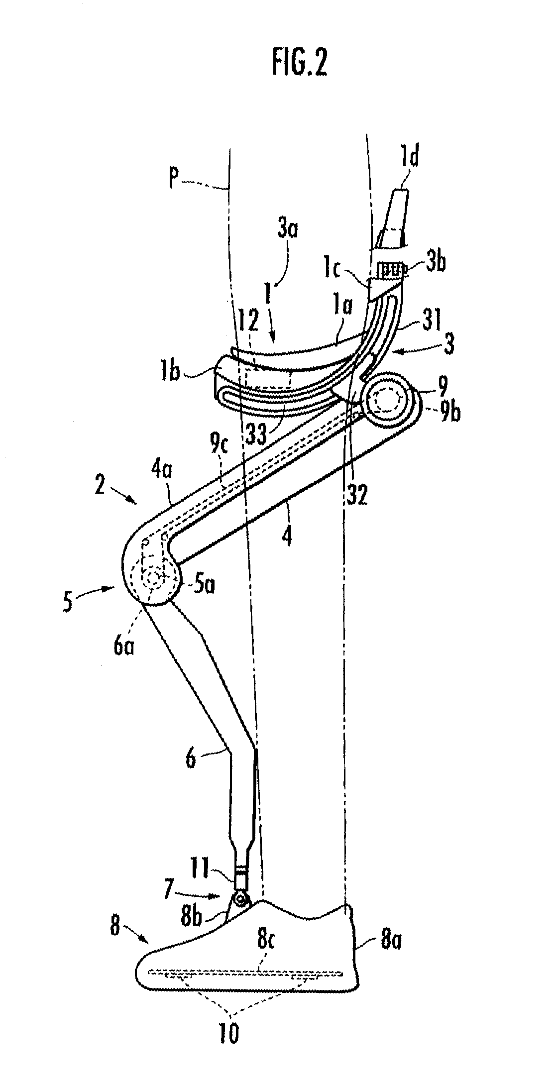
[0023]Hereinafter, a walk-assisting device of an embodiment of the invention will be described. As shown in FIGS. 1 to 3, the walk-assisting device includes a seating member 1 on which a user P sits down in a straddled posture and a pair of right and left leg links 2 and 2 which support the seating member 1 from below.

[0024]Each leg link 2 is constituted by a bendable and stretchable link including a thigh link portion 4 which is connected to the seating member 1 so as to be rockable in the front-back directions via a curved guide mechanism 3 described below, and a lower thigh link portion 6 connected to a lower end of the thigh link portion 4 via a rotary knee joint portion 5. Additionally, a foot mounting portion 8 on which one of the right and left feet of the user P is mounted is connected to a lower end of the lower thigh link portion 6 via an ankle joint portion 7.

[0025]Additionally, each leg link 2 is loaded with a drive source 9 for driving the knee joint portion 5. Also, th...


PUM


Abstract

A curved guide mechanism includes a guide unit having an arcuate guide track, and a movable body movably engaged with the guide track via a plurality of engagement elements. The guide track is constituted by a guide groove formed in the guide unit. The movable body is provided with at least three engagement elements including inner engagement elements movably engaged with an inner peripheral rail portion formed on the inner peripheral side of the guide groove, and an outer engagement element movably engaged with an outer peripheral rail portion formed on the outer peripheral side of the guide groove. The engagement elements are spaced apart from one another in a longitudinal direction of the guide groove.

Description

BACKGROUND OF THE INVENTION[0001]1. Field of the Invention[0002]The present invention relates a curved guide mechanism which guides a movable body along an arcuate guide track, and a walk-assisting device using this guide mechanism.[0003]2. Description of the Related Art[0004]In the related art, as this type of walk-assisting device, one including a seating member on which a user sits down in a straddling posture and a leg link supporting the seating member from below, and adapted to receive at least a portion of user's weight via the seating member by a leg link, thereby reducing a load acting on the user's leg to assist in his or her walking is known (for example, refer to Japanese Patent Application Laid-Open No. 2007-20909).[0005]In this walk-assisting device, the seating member and the leg link are connected together via a curved guide mechanism composed of a guide unit and a movable body. The guide unit has an arcuate guide track and is connected to the seating member. The arc...

Claims


Application Information

Patent Timeline
Patent Type & Authority Patents(United States)
IPC IPC(8): A61F5/00
CPCA61H3/008B25J9/0006A61H3/00A61H2201/1633A61H2201/5071A61H2201/1623A61H2201/1635A61H2201/1642A61H2201/165A61H2201/1676A61H2201/5061A61H2201/1215
Inventor HIKI, YUTAKA
Owner HONDA MOTOR CO LTD
Why Eureka
Try Eureka