Television unit

a technology for televisions and housings, applied in television systems, electrical equipment casings/cabinets/drawers, instruments, etc., can solve the problems of large size of the housing surrounding the display panel, disadvantage in ensuring design flexibility, and compact and thin housings, etc., to achieve the effect of reducing the size and weight of the supporting uni

Inactive Publication Date: 2010-02-16
SONY CORP
View PDF9 Cites 10 Cited by
  • Summary
  • Abstract
  • Description
  • Claims
  • Application Information

AI Technical Summary

Benefits of technology

[0011]It is desirable to provide a television unit in which the display unit can be made compact and thin, and the flexibility of design can be ensured to improve the appearance.
[0014]According to an embodiment of the present invention, the speaker is provided in the swiveling portion rather than in the display unit. Accordingly, a frame surrounding a display panel of the display unit can be reduced in size, so that it is advantageous in providing the floating feel on the display unit to the operator, thus improving the design.
[0016]Further, since the speaker is provided in the swiveling portion, the stand for supporting the display unit can be reduced in size and weight, and it is therefore advantageous in providing the floating feel to the operator.

Problems solved by technology

Accordingly, there is a limit in making the housing compact and thin, and the design of the television unit is also limited to cause a disadvantage in ensuring the flexibility of design.
However, in the case that the speaker is located at a portion of the housing on the right and left sides or on the lower side of the display panel as in the established structure, the housing surrounding the display panel becomes large in size.
In other words, the area of the housing that does not display an image becomes large, causing a disadvantage in providing the floating feel to the operator.
Further, in the case that the display unit is supported by the stand and that the speaker is provided in the display unit, the weight of the display unit supported by the stand becomes large.
Accordingly, it is necessary to make the stand large in size, causing a disadvantage in providing the floating feel to the operator.
In this case, however, the following problem may arise when the speaker is provided separately from the stand as in a separate type audio system in the past having an amplifier, tuner, and speakers are separate from each other.
When the orientation of the display unit is changed, a sound image by the sounds produced from the speaker cannot be localized in front of the display unit, causing a disadvantage such that it is difficult to provide high-quality sounds to the operator.

Method used


Image

  • Television unit
  • Television unit
  • Television unit

Examples


first preferred embodiment

[0044]A first preferred embodiment of the present invention will now be described in detail with reference to FIGS. 1 to 22.

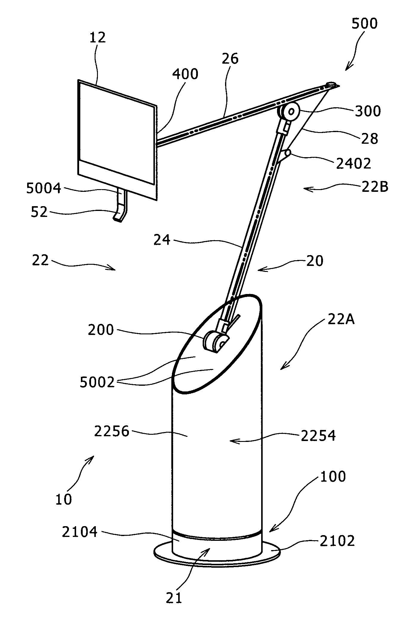
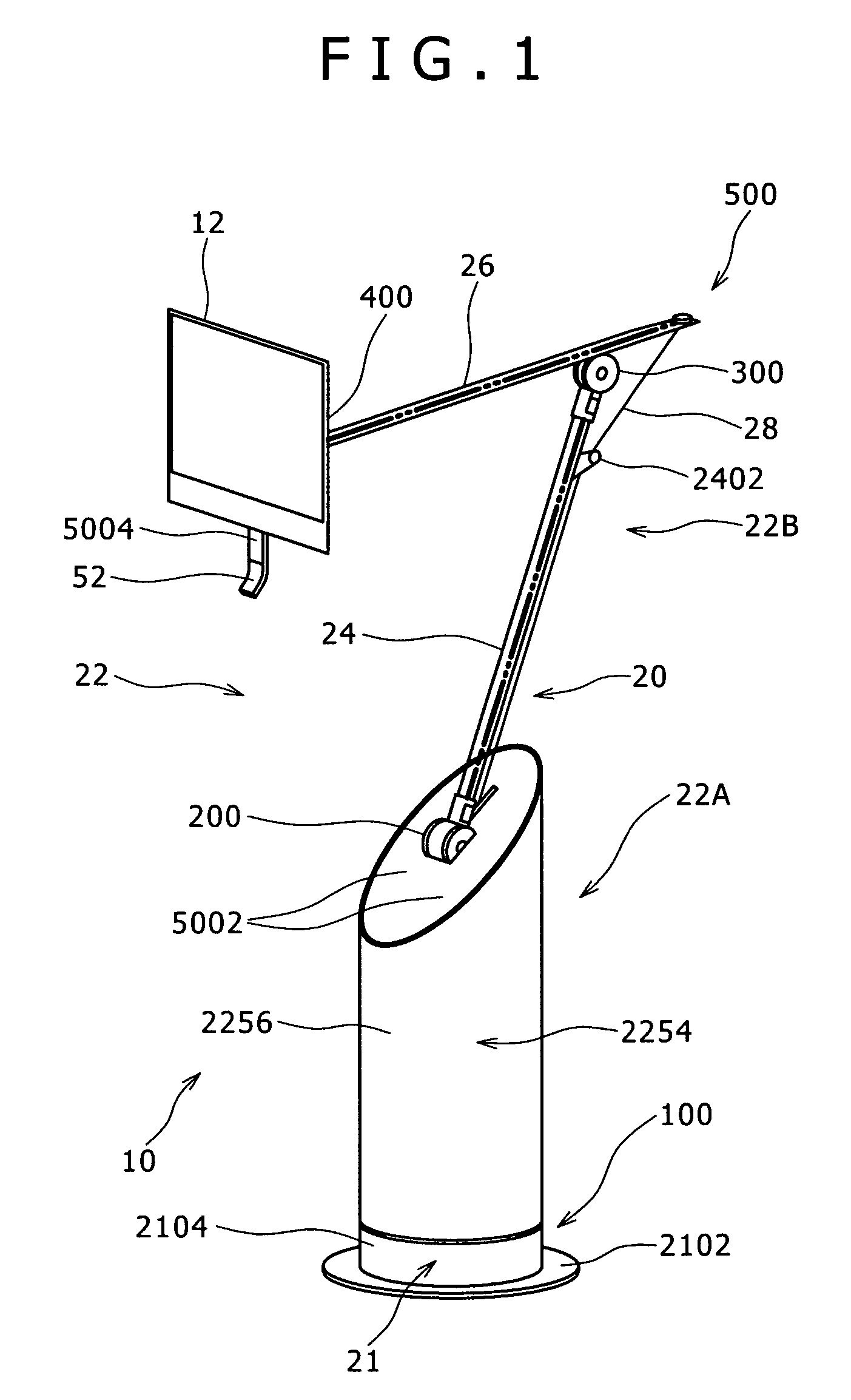
[0045]Referring to FIG. 1, there is shown a perspective view of a television unit 10 according to the first preferred embodiment of the present invention.

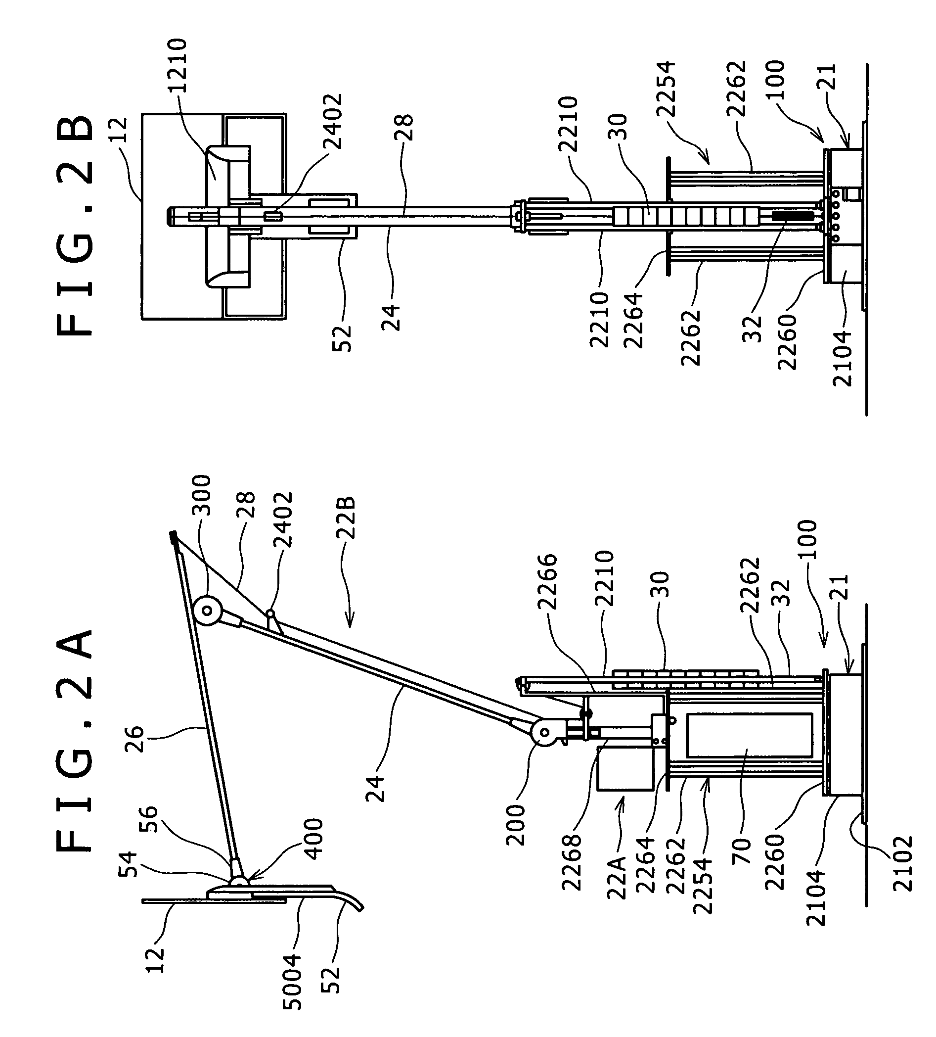
[0046]FIGS. 2A and 2B are side and rear elevations of the television unit 10, respectively. In FIGS. 2A and 2B, a cover 2256 shown in FIG. 1 is not shown for the purpose of illustration.

[0047]As shown in FIGS. 1, 2A, and 2B, the television unit 10 includes a display unit 12, a speaker 50 (see FIG. 19), and a stand 20 for supporting the display unit 12. The stand 20 includes a position changing mechanism for changeably holding the position of the display unit 12 and a tablike handle 52 for changing the position of the display unit 12.

[0048]The position changing mechanism includes a swivel mechanism 100, a first pivot portion 200, a second pivot portion 300, a third pivot portion 400, and a three-dimensional mov...

second preferred embodiment

[0154]A second preferred embodiment of the present invention will now be described with reference to FIGS. 23 and 24.

[0155]While the first speakers 5002 are provided in the lower swiveling portion 22A at the upper end thereof in the first preferred embodiment mentioned above, the position of the first speakers 5002 is not limited.

[0156]FIG. 23 is a perspective view showing a television unit 10 according to the second preferred embodiment, and FIG. 24 is a front elevation of the television unit 10 shown in FIG. 23. In the following description of the second preferred embodiment, substantially the same parts as those in the first preferred embodiment are denoted by the same reference numerals.

[0157]As shown in FIGS. 23 and 24, the first speakers 5002 are provided inside of the cylindrical wall portion of the cover 2256 in the lower swiveling portion 22A at right and left positions laterally spaced apart from each other.

[0158]More specifically, the cylindrical wall portion of the cover...


PUM


Abstract

Disclosed herein is a television unit including a thin platelike display unit, a stand for rotatably supporting the display unit, and a speaker. The stand has a mounting portion adapted to be mounted at a suitable position and a swiveling portion rotatably connected to the mounting portion for supporting the display unit. The speaker is provided in the swiveling portion of the stand.

Description

CROSS REFERENCES TO RELATED APPLICATIONS[0001]The present invention contains subject matter related to Japanese Patent Application JP 2005-333276 filed in the Japanese Patent Office on Nov. 17, 2005, the entire contents of which being incorporated herein by reference.BACKGROUND OF THE INVENTION[0002]1. Field of the Invention[0003]The present invention relates to a television unit.[0004]2. Description of the Related Art[0005]In recent years, there has been provided a television unit including a thin platelike display panel such as a liquid crystal display panel, plasma display panel, or organic electroluminescent (organic EL) display panel, a speaker for outputting sounds, and a housing for accommodating the display panel and the speaker.[0006]In many cases, the speaker is built in a portion of the housing on the right and left sides of the display panel or in a portion of the housing on the lower side of the display panel (see Japanese Patent Laid-Open No. 2005-165350).SUMMARY OF TH...

Claims


Application Information

Patent Timeline
Patent Type & Authority Patents(United States)
IPC IPC(8): H04N7/00H04N5/64
CPCF16M11/04F16M11/06F16M11/10F16M11/2021H04N5/642F16M2200/044
Inventor SAKATA, TATSUYASHIRAISHI, YOSHITOMIKI, YUTAKAKOIZUMI, EIJIARAKI, TOMOMI
Owner SONY CORP
Why Eureka
Try Eureka