
Integrated hydraulic pump directly driven by slotless moving magnet type linear oscillation motor

A technology of oscillating motor and hydraulic pump, applied in the field of hydraulic pump, can solve the problems of reducing the reliability and stability of the whole machine operation, increasing the difficulty of assembling the electromagnetic direct drive pump, and being difficult to realize two-way drive, etc., so as to improve the heat dissipation efficiency and limit work. capacity, is conducive to the layout of the external cooling system, and is conducive to the effect of miniaturized design

Inactive Publication Date: 2021-04-02
DALIAN UNIV OF TECH
View PDF3 Cites 0 Cited by
  • Summary
  • Abstract
  • Description
  • Claims
  • Application Information

AI Technical Summary

Problems solved by technology

However, with the moving coil as the driving part, the coil outlet must be arranged in a special way, which makes it difficult to achieve integrated two-way drive, which increases the difficulty of assembly of the electromagnetic direct drive pump, and mostly operates in a single-piston multi-pump drive mode.
At the same time, the moving coil built between the yoke and the permanent magnet is used as a heat source, the heat cannot be dissipated in time, and the temperature rise is obvious, which reduces the reliability and stability of the whole machine

Method used


Image

  • Integrated hydraulic pump directly driven by slotless moving magnet type linear oscillation motor
  • Integrated hydraulic pump directly driven by slotless moving magnet type linear oscillation motor

Examples


Embodiment 1

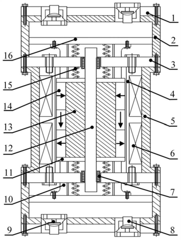
[0041] Such as figure 1 As shown, an integrated hydraulic pump directly driven by a slotless moving magnet linear oscillating motor includes: a hydraulic pump stator, a hydraulic pump mover and a resonant spring 15 arranged in the hydraulic pump stator, and the resonant spring 15 is connected to the hydraulic pump motor child connected. The stator of the hydraulic pump consists of two valve bodies 1, two hydraulic cylinders 2, two end covers 3, a coil skeleton 4, an outer yoke 5, an electromagnetic coil group 6, a liquid inlet check valve 8 and a liquid outlet check valve 9 composed of symmetrical structures. The mover of the hydraulic pump is composed of two piston connecting bodies 10 , two magnetic isolation protection rings 11 , a drive shaft 12 , a mover yoke 13 , a permanent magnet array 14 and two pistons 16 . A liquid inlet check valve 8 and a liquid outlet check valve 9 are respectively installed on the upper and lower valve bodies 1 . The materials of the outer yo...


PUM


Abstract

The invention provides an integrated hydraulic pump directly driven by a slotless moving magnet type linear oscillation motor. The integrated hydraulic pump comprises a hydraulic pump stator, a hydraulic pump rotor and a resonance spring, wherein an electromagnetic coil group in the hydraulic pump stator is coaxially and fixedly connected with two end covers; two hydraulic cylinder barrels are coaxially and fixedly connected to the outer end parts of the two end covers; two valve bodies are coaxially, hermetically and fixedly connected to the outer end parts of the two hydraulic cylinder barrels; liquid-distributing one-way valves are symmetrically mounted in through holes in the two ends of the valve bodies and the hydraulic cylinder barrels; a permanent magnet array in the hydraulic pumprotor is arranged in a Halbach array mode, attached to the outer surface of a rotor yoke in a surface-mounted mode and coaxially fixed to a driving shaft; magnetic isolating protection rings are adhered to the two ends of the rotor yoke; two piston connecting bodies are coaxially fixed with the two magnetism isolating protection rings and are respectively connected with two pistons; and resonancesprings are arranged between the pistons and the magnetism isolating protection rings in a sleeved way. The hydraulic pump stator, the hydraulic pump rotor and the resonance springs jointly form a resonance system. The integrated hydraulic pump is compact in structure and high in power density, and the working efficiency of the hydraulic pump can be effectively improved.

Description

technical field [0001] The invention relates to the technical field of hydraulic pumps, in particular to an integrated hydraulic pump directly driven by a slotless moving magnet linear oscillating motor. Background technique [0002] Compared with the traditional swash plate plunger hydraulic pump, the electromagnetic direct drive hydraulic pump cancels the "rotary-linear" motion conversion mechanism in the middle, shortens the power transmission route, and has the advantages of simple flow adjustment method, large rated flow, and high power density. , which is convenient for high-integration integrated design and miniaturized design, and can be applied to fields such as aviation electric hydrostatic actuators, automotive metering pumps and engineering hydraulic machines with large flow, variable flow, high precision and high pressure. [0003] As the power source and drive device of the electromagnetic direct drive pump, the linear oscillatory motor directly determines the ...

Claims


Application Information

Patent Timeline
Patent Type & Authority Applications(China)
IPC IPC(8): H02K33/02H02K1/34F04B17/04F04B1/02
CPCF04B1/02F04B17/04H02K1/34H02K33/02
Inventor 高仁璟王赓吕治强王奇
Owner DALIAN UNIV OF TECH
Learn More