Ticket dispensing modules and method

a ticket and module technology, applied in the field of ticket dispensers, vending machines and methods, can solve the problems of thwarting the desires of some customers, complex and expensive construction and maintenance, and large separation mechanism currently used, and achieves the effects of reducing the number of tickets sold

Inactive Publication Date: 2010-02-23
GTECH CORP
View PDF117 Cites 50 Cited by
  • Summary
  • Abstract
  • Description
  • Claims
  • Application Information

AI Technical Summary

Problems solved by technology

In the type of dispenser in which tickets are burst free from the strip, there are several significant problems.
One of the main problems is that the separating mechanism currently used is relatively large, complex, and expensive to build and maintain.
Another problem with such prior dispensers is that the most common of such dispensers burst each and every ticket free from the strip.
This tends to thwart the desires of some customers who would prefer to receive a string of connected tickets.
A further problem is with the loading of tickets into a multi-bin lottery ticket dispensing machine.
This is time-consuming, laborious, and error-prone.
Another problem with such systems is that winning tickets usually require verification.
Although this procedure minimizes certain kinds of errors and fraud, it does not detect a ticket which has come into the possession of the holder by means other than its actual dispensation from a vending machine.
Another problem with instant-winner gaming tickets is that a relatively large variety of different games are developed in order to keep the ticket buyers' interest.
This creates additional costs for the lottery ticket issuing organization, requires more dispensing bins per vending machine, and / or more vending machines to dispense the multitude of games.
It is another problem with ticket vending systems that they do not provide accounting for all of the tickets dispensed by the vending machines in the system.

Method used


Image

  • Ticket dispensing modules and method
  • Ticket dispensing modules and method
  • Ticket dispensing modules and method

Examples


Embodiment Construction

[0040]It is an object of the present invention to provide a ticket dispenser and vending machine which separates tickets from one another, and yet has a separator mechanism which is relatively simple in construction and operation, and is relatively compact and inexpensive to manufacture and maintain.

[0041]In addition, it is an object of the invention to provide such a dispenser and vending machine in which tickets can be issued either singly or in strips of several tickets fastened together, as desired by the customer.

[0042]An additional object of the invention is to provide such a separator mechanism which requires relatively low levels of force to be applied to create the separating action.

[0043]A further object of the invention is to provide a vending machine and method in which initializing each machine and loading it with tickets requires less time and labor, and is less subject to error.

[0044]It also is an object of the invention to provide a lottery ticket dispensing system a...


PUM

PropertyMeasurementUnit
angleaaaaaaaaaa
areasaaaaaaaaaa
motive poweraaaaaaaaaa

Abstract

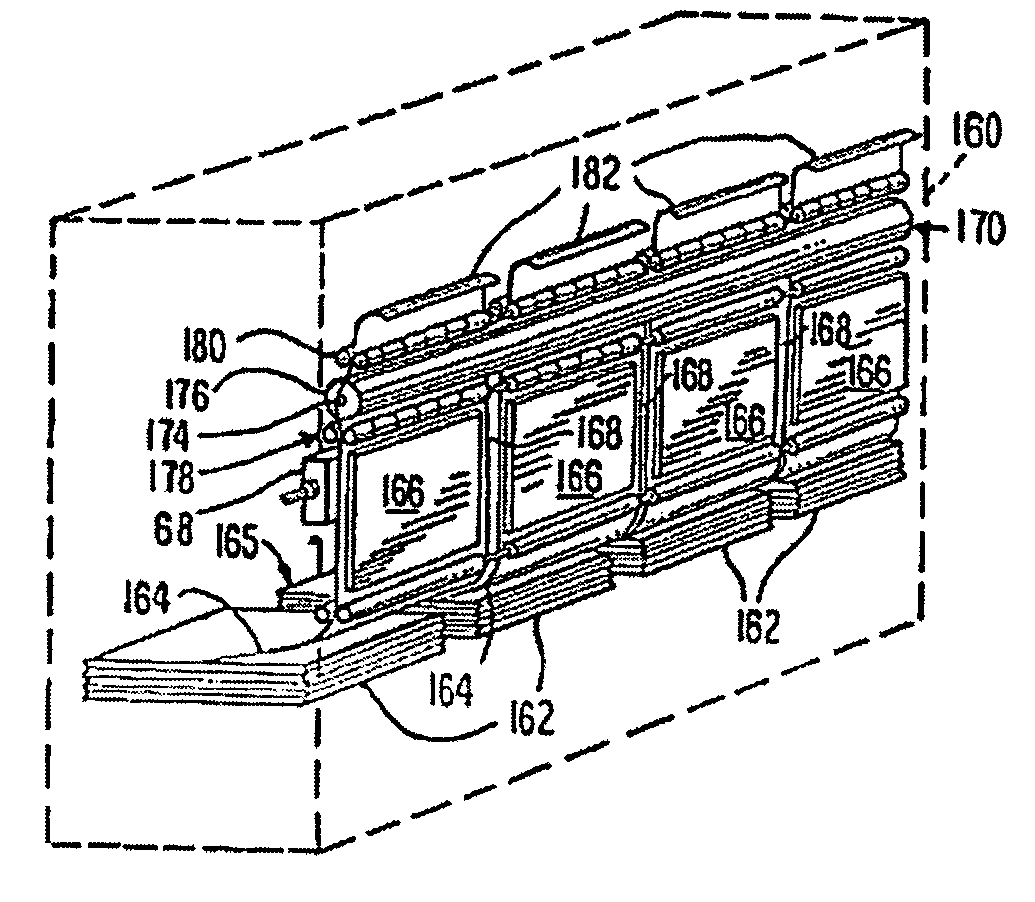
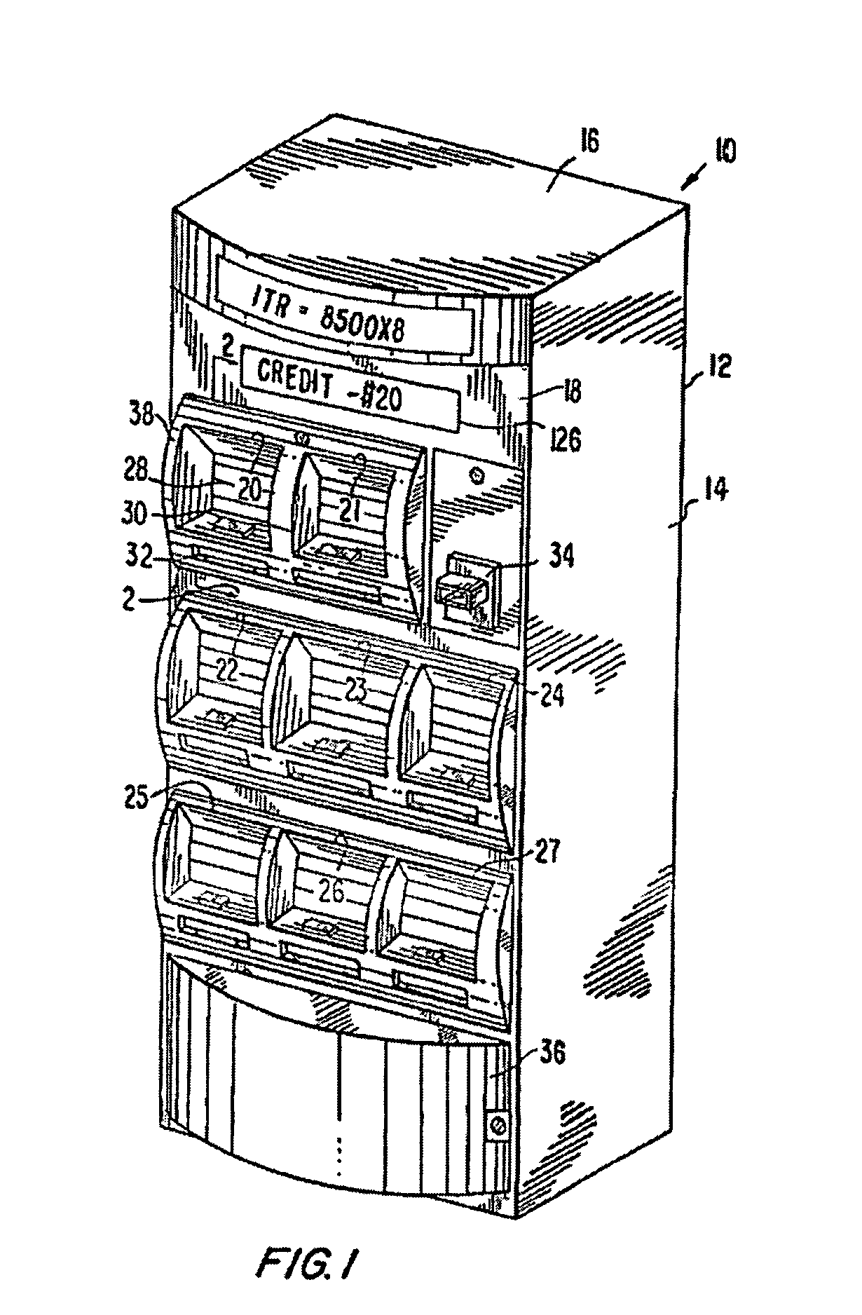
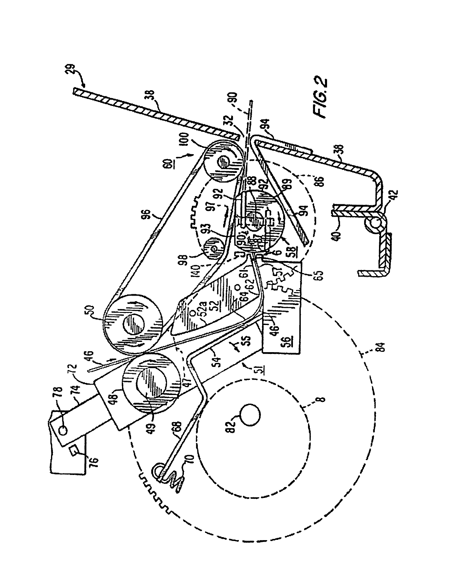
The dispenser dispenses tickets such as instant-winner lottery tickets from a strip in which the individual tickets are delineated by perforation lines. The dispenser includes a separator to tear the tickets apart before issuing them from the machine. The separator preferably is rotary and has a dull helical blade which rotates to contact the ticket strip adjacent a perforation line, and presses against the strip to tear the tickets apart along the perforation line at a point which progresses across the strip along the perforation line. Preferably, a bar code reader is provided for reading codes on tickets in the dispensing machine. The bar code reader is used in reading information from the tickets to initialize the dispenser control system and in accounting for the sale of tickets, and in the verification of winning tickets being sold. A game is provided in which the concept is that a jackpot is built up using the detection of each ticket sold. The mechanism is simplified by using a separator member and transport drive structures which span a plurality of different channels or bins of a multi-channel dispenser. This provides a very compact, simple, secure and low-cost mechanism which is used both in stand-alone ticket vending machines, and in counter-top attended dispensers.

Description

CROSS-REFERENCE TO RELATED APPLICATIONS[0001]This application is a continuation-in-part of U.S. patent application Ser. No. 09 / 385,336, filed Aug. 30, 1999 now U.S. Pat. No. 6,932,258. U.S. patent application Ser. No. 09 / 385,336 is a continuation-in-part of now U.S. Pat. No. 6,348,744 U.S. patent application Ser. No. 09 / 060,426, filed on Apr. 14, 1998, of abandoned U.S. patent application Ser. No. 09 / 128,406, filed Aug. 3, 1998, and of U.S. patent application Ser. No. 09 / 238,682, filed Jan. 26, 1999. U.S. patent application Ser. No. 09 / 238,682 issued as U.S. Pat. No. 6,726,077.[0002]A portion of the disclosure of this patent document contains material that is subject to copyright protection. The copyright owner has no objection to the facsimile reproduction by anyone of the patent document or patent disclosure as it appears in the Patent and Trademark Office patent file or records, but otherwise reserves all copyright rights whatsoever.BACKGROUND INFORMATION[0003]This invention rela...

Claims


Application Information

Patent Timeline
Patent Type & Authority Patents(United States)
IPC IPC(8): B26D7/06A63F1/18B26F3/00B65G47/14B65G59/00
CPCG07F11/68G07F17/32G07F17/329Y10T83/101Y10T225/211Y10T225/12Y10T83/2216Y10T225/10Y10T225/314Y10T83/4448Y10T83/4804Y10T83/343Y10T225/35Y10T225/205
Inventor ROBERTS, BRIAN J.PETCH, DAVID B.
Owner GTECH CORP
Why Eureka
Try Eureka