Fuel vapor control devices

a technology of fuel vapor and control device, which is applied in the direction of electric control, combustion air/fuel air treatment, machines/engines, etc., can solve the problems of relative displacement and other problems, and achieve the effect of reducing the amount of fuel vapor to be fed to the canister, reducing the volume of the fuel tank, and simplifying the constitution of the devi

Active Publication Date: 2010-02-23
AISAN IND CO LTD
View PDF6 Cites 11 Cited by
  • Summary
  • Abstract
  • Description
  • Claims
  • Application Information

AI Technical Summary

Benefits of technology

[0008]One aspect according to the present invention includes fuel vapor control devices that include a fuel tank for storing fuel, a canister for adsorbing fuel vapor produced in the fuel tank, and an evaporation path communicating between the fuel tank and the canister. The tank has a resiliently deformable wall portion that can resiliently deform in response to an amount of the fuel vapor in the fuel tank, so that volume of the fuel tank can be varied. A pressure regulating valve that can perform a relief function for opening the evaporation path during the expansion of volume of the fuel tank to a set volume. The pressure regulating valve closes the evaporation path if pressure inside the fuel tank is lower than the set value. On the other hand, the pressure regulating valve opens the evaporation path if the pressure inside the fuel tank is equal to or higher than the set value. Under this condition, until the volume of the fuel tank is expanded to the set volume, resilient deformation of the resiliently deformable wall portion of the fuel tank absorbs the change of the pressure inside the tank, and accordingly, the amount of the fuel vapor to be fed to the canister may be decreased. In this way, the variable volume container and the communicating path connected to the variable volume container which are required for the conventional fuel vapor control device may be omitted and constitution of the device may be simplified. If the pressure inside the tank is equal to or higher than the set value, the pressure regulating valve opens the evaporation path and the pressure is released via the evaporation path to the canister. When the pressure inside the fuel tank decreases to be lower than the set value, the pressure regulating valve closes the evaporation path.
[0009]In one embodiment, the pressure regulating valve opens the evaporation path without performing a relief function when an internal combustion engine is operating. Accordingly, the pressure inside the tank is maintained to be low. Under this condition, if the internal combustion engine is stopped, the pressure regulating valve starts to perform the relief function on the condition that the pressure inside the tank is low. Due to this, the amount of the fuel vapor stored in the fuel tank may be increased compared to the case where pressure regulating valve starts the relief function on the condition that the pressure inside the tank is high. Accordingly, the amount of the fuel vapor to be fed to the canister may be reduced.
[0010]In another embodiment, if the fuel is charged, the pressure regulating valve opens the evaporation path without performing the relief function. Then, the fuel vapor inside the fuel tank is fed into the canister, and accordingly, the pressure inside the tank is decreased. Under this condition, if the volume of the tank is expanded due to the resilient deformation of the resiliently deformable wall portion of the fuel tank, the evaporation path is opened. Then, the volume of the tank is reduced with the resilient restoration of the resiliently deformable wall portion of the fuel tank to the original state. Accordingly, it is possible to prevent or inhibit the fuel vapor from being ejected into atmosphere when a fuel filling port is opened.
[0011]In a further embodiment, the pressure regulating valve is disposed on the wall portion of the fuel tank. Therefore, potential damage to the evaporation path that may be caused by the relative displacement between the fuel tank and the pressure regulating valve may be prevented or inhibited. Such relative displacement may be caused, for example, due to removal of a hose and mutual friction of the connected portions when the hose is used for the evaporation path.

Problems solved by technology

Such relative displacement may be caused, for example, due to removal of a hose and mutual friction of the connected portions when the hose is used for the evaporation path.

Method used


Image

  • Fuel vapor control devices
  • Fuel vapor control devices

Examples


embodiment 1

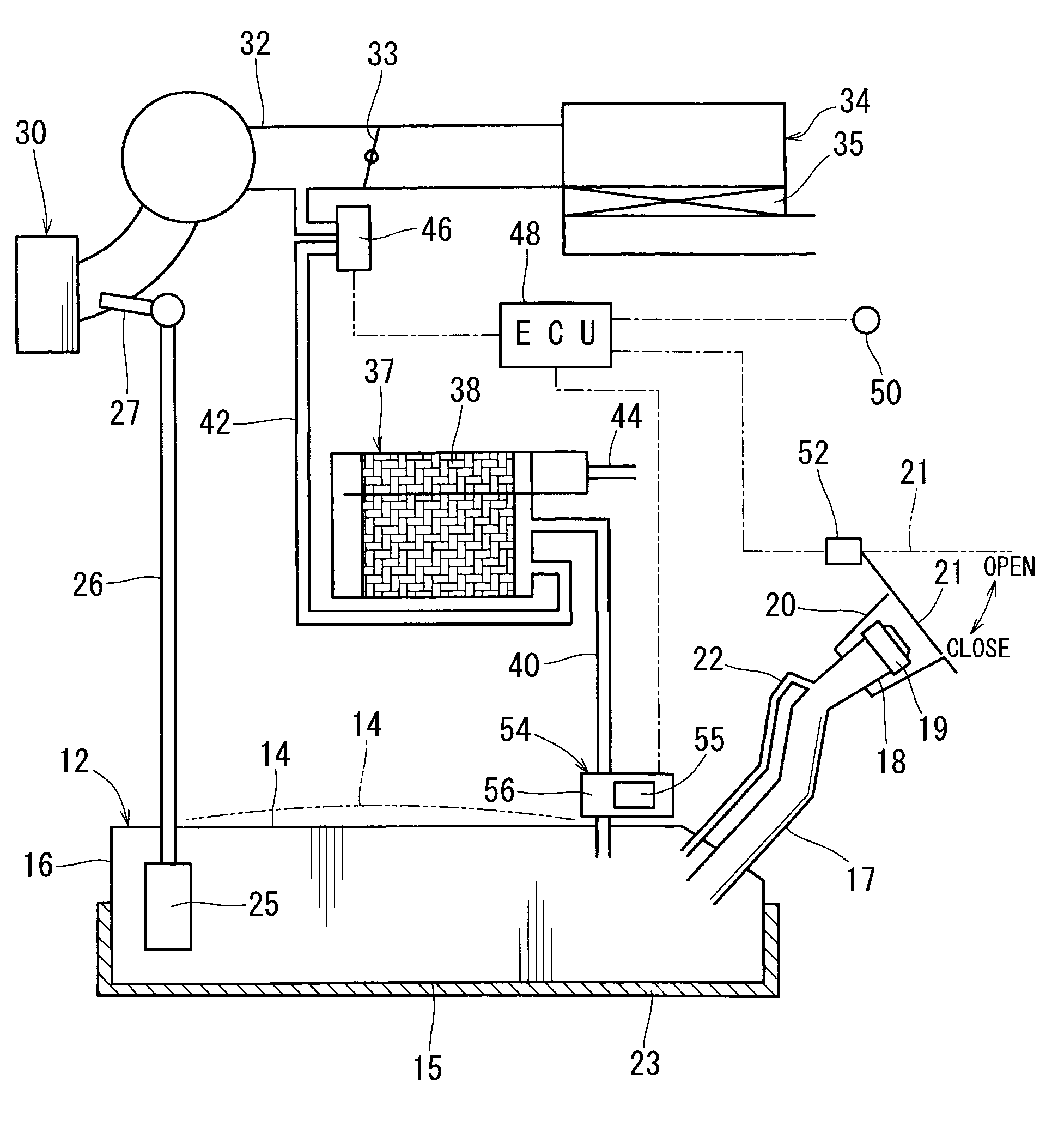
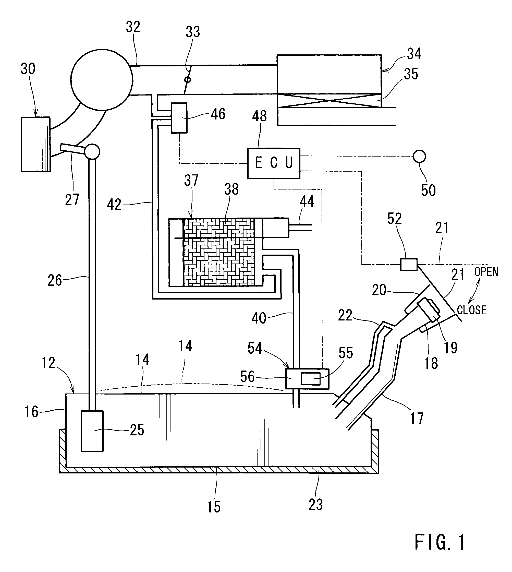
[0016]A first embodiment of the present invention will be explained below. This embodiment relates to a fuel vapor control device for a vehicle. FIG. 1 is a structural view showing the fuel vapor control device. As shown in FIG. 1, a fuel tank 12 for storing fuel (specifically, liquid fuel) has a hollow configuration and is installed on a vehicle, such as an automobile (not shown). The fuel tank 12 is, for instance, made of resin and has an upper wall portion 14, a bottom wall portion 15 and a peripheral wall portion 16. The upper wall portion 14, the bottom wall portion 15 and the peripheral wall portion 16 constitute “wall portions of the tank.”

[0017]The upper wall portion 14 of the fuel tank 12 can resiliently or flexurally deform, so that the upper wall portion 14 can expand upwardly in a curved manner by pressure inside the tank (see, two-dot chain line 14 in FIG. 1). Because of the resilient deformation of the upper wall portion 14, the volume of the tank 12 may be variable, i...


PUM


Abstract

A fuel vapor control device include a fuel tank for storing fuel, a canister for adsorbing fuel vapor produced in the fuel tank, and an evaporation path communicating between the fuel tank and the canister. The tank has a resiliently deformable wall portion that can resiliently deform in response to an amount of the fuel vapor in the fuel tank, so that volume of the fuel tank can be varied. A pressure regulating valve can perform a relief function for opening the evaporation path during the expansion of volume of the fuel tank to a set volume. The pressure regulating valve closes the evaporation path if pressure inside the fuel tank is lower than the set value. On the other hand, the pressure regulating valve opens the evaporation path if the pressure inside the fuel tank is equal to or higher than the set value.

Description

[0001]This application claims priority to Japanese patent application serial number 2007-195805, the contents of which are incorporated herein by reference.BACKGROUND OF THE INVENTION[0002]1. Field of the Invention[0003]The present invention relates, to fuel vapor control devices used mainly for an internal combustion engine installed on a vehicle.[0004]2. Description of the Related Art[0005]A conventional fuel vapor control device is shown in Japanese Laid-Open Patent Publication No. 11-34675. The fuel vapor control device disclosed in the Publication No. 11-34675 includes a fuel tank for storing fuel, a canister for adsorbing fuel vapor produced in the fuel tank, an evaporation path for communicating between the fuel tank and the canister, and a pressure regulating valve for opening and closing the evaporation path. Specifically, the pressure regulating valve closes the evaporation path when pressure inside the tank is less than a set value, and opens the evaporation path when the...

Claims


Application Information

Patent Timeline
Patent Type & Authority Patents(United States)
IPC IPC(8): F02M33/02
CPCB60K15/03504F02D41/0032F02M25/0836F02M25/089F02M37/0076
Inventor SHINAGAWA, MASANOBUTAKAMATSU, HIROSHI
Owner AISAN IND CO LTD
Why Eureka
Try Eureka