
Water ride attraction

a technology for water rides and attractions, applied in the field of water rides, can solve the problems of choking the entire flow, localized subcritical flow, and impairing the rider in his, and achieve the effects of less skill to catch and ride, and less difficulty in catching and riding

Inactive Publication Date: 2010-02-23
WHITEWATER WEST INDS
View PDF97 Cites 22 Cited by
  • Summary
  • Abstract
  • Description
  • Claims
  • Application Information

AI Technical Summary

Benefits of technology

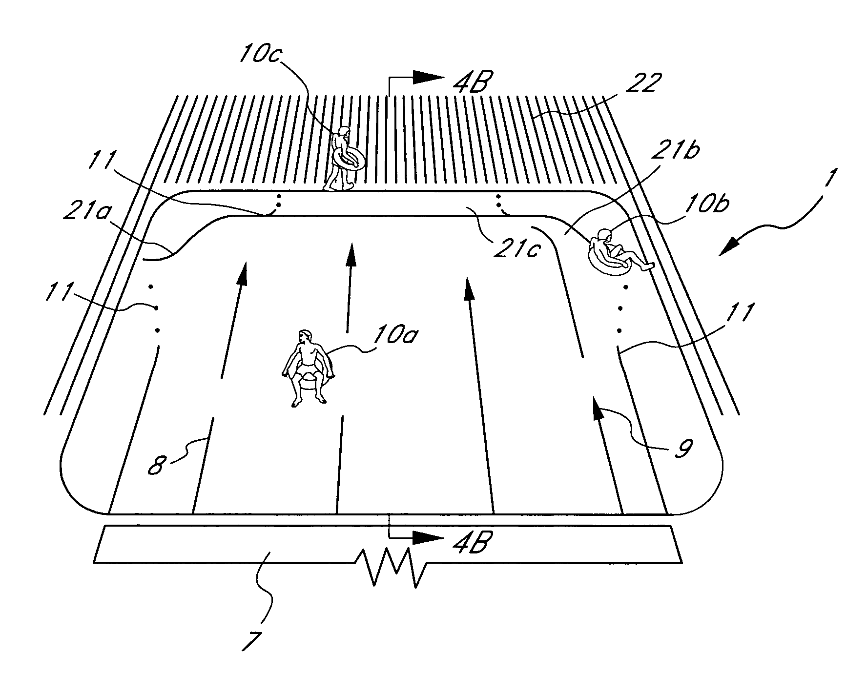
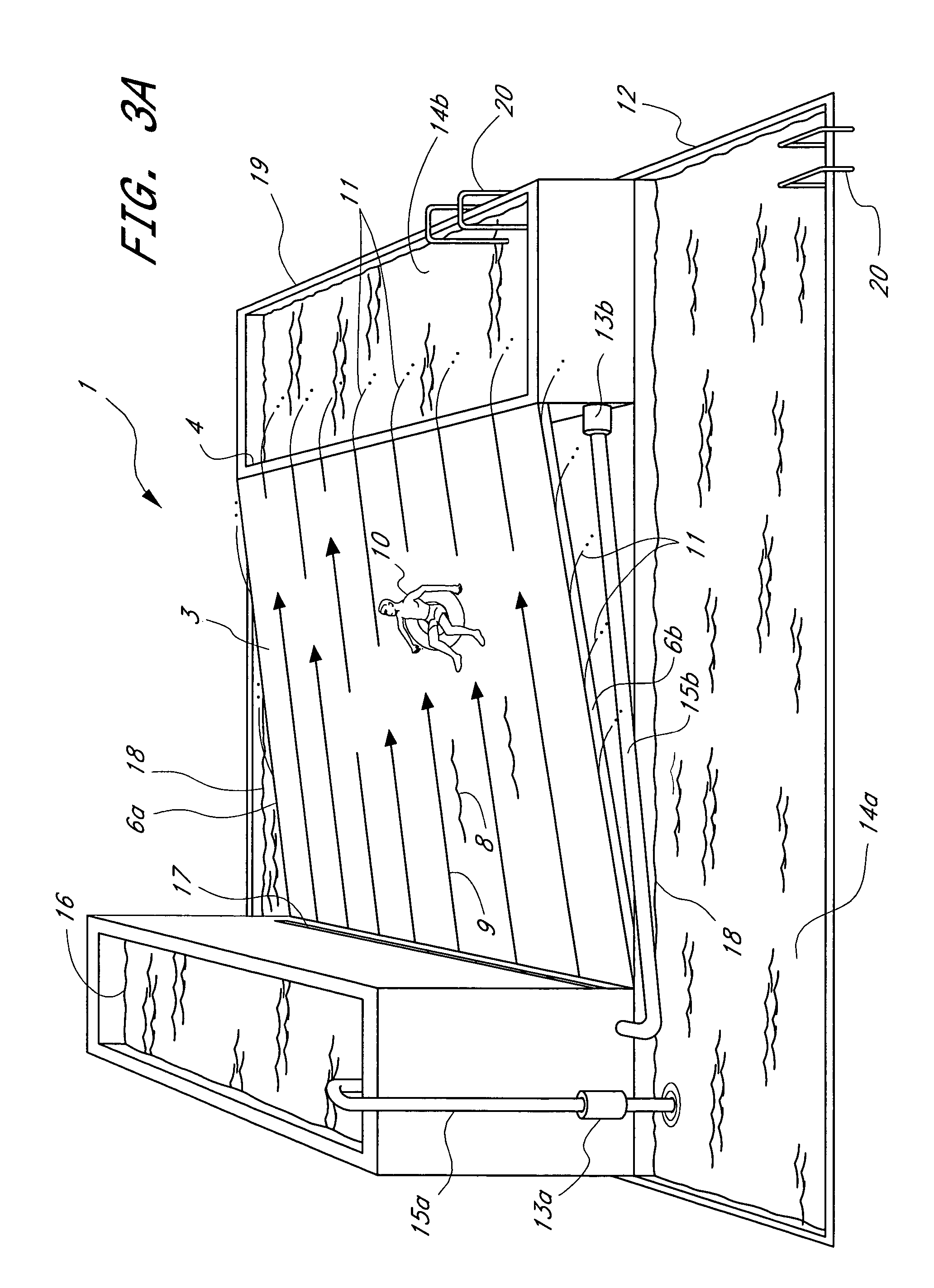
The present invention provides an improved stationary wave forming apparatus and method that eliminates boundary layer induced subcritical flow and associated flow disturbances that greatly affect wave quality. The invention uses a containerless incline that prevents the formation of oblique waves and allows for a more stable ride. The preferred water flow type is a relatively thin sheet flow, which is more stable than deeper water flows. The invention also provides a separation streamline that prevents critical and subcritical flow over the top and back of an obstacle, resulting in an illusion of a large wave. The invention can be adapted to various wave conditions and parameters.

Problems solved by technology

That is, during the operation of a wave making apparatus having side wall containment, drag forces along the side walls result in localized subcritical flow.
Since this gain in energy results in a gain in amplitude as the oblique waves move downhill against the current, they create a “chop” which not only impairs a rider in his performance of water skimming maneuvers, but also propagates and leads to choking of the entire flow.

Method used


Image

  • Water ride attraction
  • Water ride attraction
  • Water ride attraction

Examples


Embodiment Construction

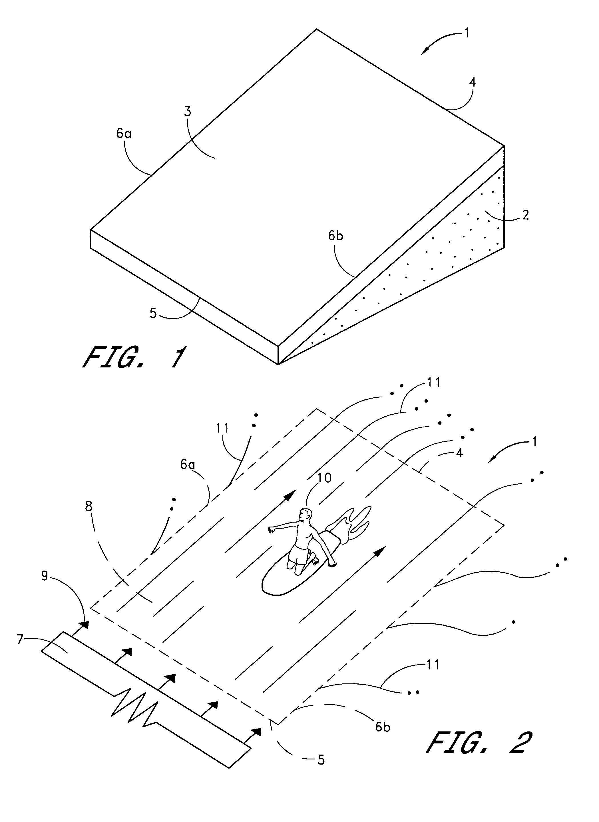
[0116]FIG. 1 shows one embodiment of a containerless incline 1 of the present invention. Plan-sectional lines as revealed in FIG. 1 are solely for the purpose of indicating the three-dimensional shape in general, rather than being illustrative of specific frame, plan, and profile sections. In fact, it should be noted that a wide variety of dimensions and configurations for a containerless incline are compatible with the principles of the present invention. Therefore, these principles should-not be construed to be limited to any particular configuration illustrated in the drawings or described herein.

Containerless Incline

[0117]Containerless incline 1 is comprised of sub-surface structural support 2, and ride surface 3 which is bounded by a downstream ridge edge (line) 4, an upstream edge 5, and side edges 6a and 6b. Ride surface 3 can be a skin over sub-surface structural support 2, or can be integrated therewith so long as sufficiently smooth. If a skin, ride surface 3 can be fabric...


PUM


Abstract

A water ride attraction is disclosed which utilizes a containerless riding surface to eliminate disadvantageous boundary layer effects. A sheet flow of water is directed up the incline to produce a simulated wave. The configuration and contour of the riding surface and the various flow parameters can be widely varied to produce numerous desirable wave conditions.

Description

RELATED APPLICATIONS[0001]This application is a continuation of U.S. Ser. No. 10 / 010,163, filed Nov. 16, 2001, now U.S. Pat. No. 6,716,107 which is a continuation of Ser. No. 09 / 594,386, filed Jun. 13, 2000, now U.S. Pat. No. 6,319,137, issued Nov. 20, 2001, which is a continuation of Ser. No. 09 / 265,722, filed Mar. 9, 1999, now U.S. Pat. No. 6,132,317, issued Oct. 17, 2000, which is a continuation of Ser. No. 08 / 826,902, filed Apr. 9, 1997, now U.S. Pat. No. 5,899,633, issued May 4, 1999, which is a continuation of Ser. No. 08 / 398,158, filed Mar. 3, 1995, now U.S. Pat. No. 5,628,584, issued May 13, 1997, which is a division of Ser. No. 07 / 866,073, filed Apr. 1, 1992, now U.S. Pat. No. 5,401,117, issued Mar. 28, 1995, which is a continuation of U.S. Ser. No. 07 / 722,980, filed Jun. 28, 1991, abandoned, which is a continuation-in-part of Ser. No. 07 / 577,741, filed Sep. 4, 1990, now U.S. Pat. No. 5,236,280, issued Aug. 17, 1993. Each of these related applications is hereby incorporated...

Claims


Application Information

Patent Timeline
Patent Type & Authority Patents(United States)
IPC IPC(8): A63G21/18A63H23/10A63B69/00A63C19/00A63C19/10A63G3/00A63G3/02A63G31/00B63B35/85E04H4/00
CPCA63B69/0093A63C19/00A63G3/02A63G31/00A63G31/007B63B35/85E04H4/0006A63B2208/12A63G21/18Y02E10/28Y02E10/30Y02E10/20
Inventor LOCHTEFELD, THOMAS J.
Owner WHITEWATER WEST INDS
Learn More