Safety switch

a safety switch and switch body technology, applied in the field of safety switches, can solve the problems of driving cams, /b> being detrimentally configured, foreign substances entering the safety switch must be taken, etc., and achieve the effect of increasing the mounting freedom of the safety switch, wide choice of places, and high degree of freedom

Active Publication Date: 2010-02-23
IDEC CORPORATION
View PDF18 Cites 6 Cited by
  • Summary
  • Abstract
  • Description
  • Claims
  • Application Information

AI Technical Summary

Benefits of technology

[0019]According to the first aspect of the invention, the relation between the actuator entrance hole and the cable lead-out port provides such a high degree of freedom with respect to the cable lead-out direction as to permit the safety switch to be installed on the wall surface or the protective door. Further, the actuator entrance hole may be oriented horizontally and vertically. In addition, the safety switch may be installed with either side (the front or back side) thereof firmly attached to the installation place. Thus, the safety switch is increased in the mounting freedom, so as to offer a wider choice of place to mount the safety switch. The switch body includes only one actuator entrance hole, obviating the actuator entrance hole left unused. Hence, the safety switch is prevented from suffering failure caused by the foreign substances invading through the unused actuator entrance hole. The switch body includes only one actuator entrance hole so that the driving cam may be so configured as to receive the actuator entering in one direction. Hence, the driving cam may be formed with one engaging portion and one cam curve portion in spaced relation. The driving cam itself may be increased in strength, as obviating the area having the poor strength. This results in the increased durability of the safety switch. Further, the protrusion of the bent cable may be minimized because the cable lead-out port is formed at the opposite corner portion to the actuator entrance hole. This negates the need for providing such a large space to allow for the cable bending as provided in the conventional safety switch. Accordingly, the safety switch is subjected to less locational constraints.
[0020]According to the second aspect of the invention, the cable led out through the cable lead-out port may be bent at the angle of about 45° relative to the lead-out port, preventing the bent cable from protruding from the switch body. The two peripheral surfaces adjoining the slant surface, formed with the lead-out port, may be firmly attached to the wall surface or the like for installation of the safety switch. Therefore, the safety switch is further increased in the mounting freedom, allowing for an even wider choice of place to mount the safety switch.
[0021]According to the third aspect of the invention, all the outside surfaces of the safety switch, except for the peripheral surface formed with the actuator entrance hole, may be firmly attached to the wall surface or the like for installation of the safety switch. Therefore, the safety switch is increased in the mounting freedom, allowing for the wider choice of place to mount the safety switch.

Problems solved by technology

This involves a problem that measure against the invasion of foreign substances into the safety switch must be taken.
That is, a problem exists that the driving cams 151, 152 are detrimentally configured to include an area having a poor strength.
This results in a problem that the location of the safety switch is limited.

Method used


Image

  • Safety switch
  • Safety switch
  • Safety switch

Examples


first embodiment

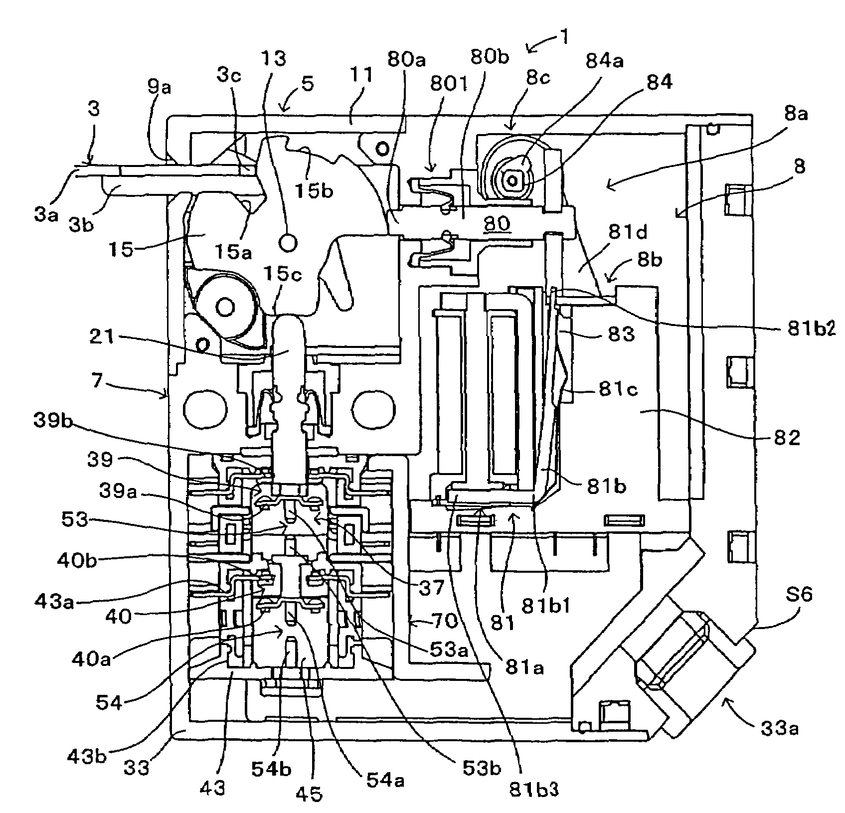
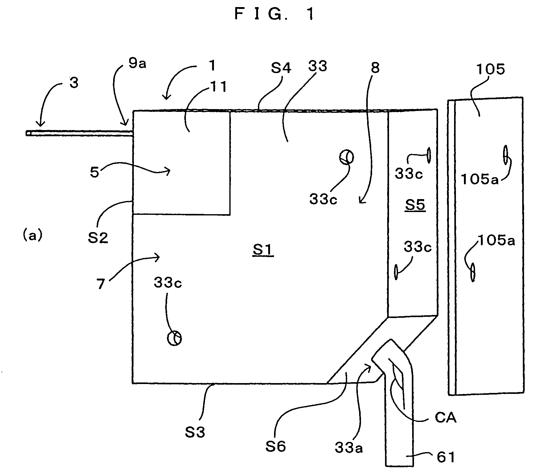
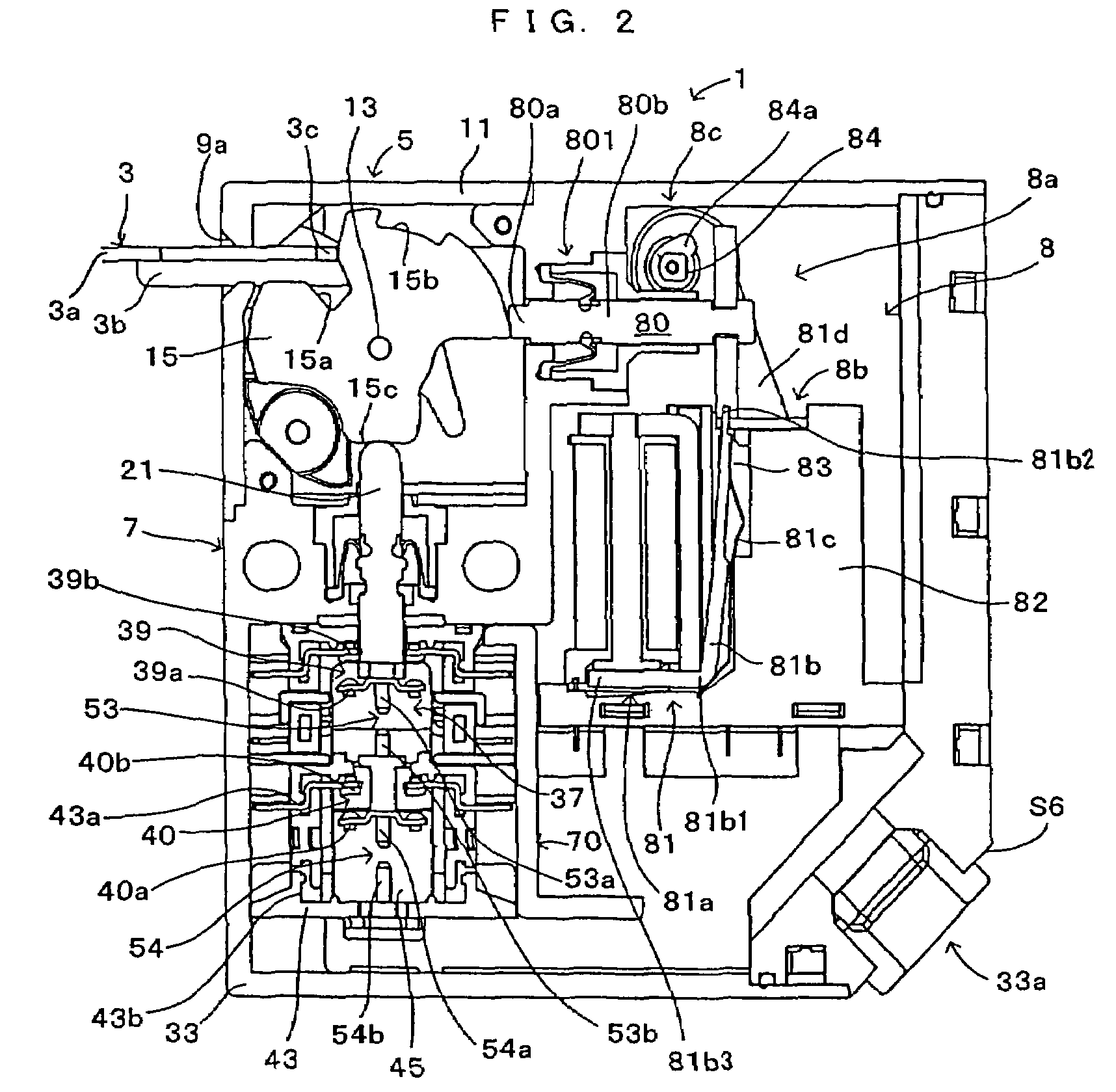
[0035]A first embodiment of the invention will be described with reference to FIG. 1 to FIG. 9. FIG. 1 is an external view of a safety switch. FIG. 2 to FIG. 5 are sectional views of a switch body. FIGS. 6A to 6D are a sectional view of a lock switching device. FIGS. 7A and 7B are an external view of the safety switch. FIG. 8 is an enlarged view of a driving cam. FIG. 9 is an enlarged view of an operation portion.

[0036]Similarly to the conventional safety switch as described above, a safety switch according to the invention is electrically connected with industrial machines such as a robot as an external apparatus by means of a cable. As shown in FIG. 1, the safety switch comprises a switch body 1 and an actuator 3. The switch body 1 has a constitution wherein removably attachable first case member 11 and second case member 33 are unified with each other to form a rectangular solid. At a corner portion (equivalent to “one corner portion” of the invention) defined by peripheral surfa...

second embodiment

[0078]As a second embodiment of the invention, a lock body unit 802 may be constituted such that a lock body 802d is supported by a lock-body supporting portion 802c and seal members 802a, 802b, as shown in FIG. 10. In this case, the lock body unit 802 may be disposed at place upwardly of the hinge-shaped electromagnet 81a constituting the driver in a manner that the lock body unit is removably assembled in the driver. The lock body 802d comprises a base 802e and a distal end 802f continuous to the base 802e. A hole 802g for reducing the breaking strength may be formed by drilling a boundary portion between the base 802e and the distal end 802f.

[0079]The following advantage may be provided by unitizing the lock body 802d as the lock body unit 802 and removably assembling the unit in the driver. If the lock body 802d should be broken, the safety switch may be quickly and efficiently restored by replacing the lock body unit 802. The lock body 802d is formed with the hole 802g for red...

third embodiment

[0080]A third embodiment of the invention may be constituted as follows. As shown in FIG. 11, a driver 181 is provided which comprises: a hinge-shaped electromagnet 181a similar to the hinge-shaped electromagnet 81a of the first embodiment; a bias spring 181c comprising a coil spring or the like for biasing an upper end of an action body 181b rightward; and a link body 181d for transferring the displacement of the action body 181b to the lock body 80. The hinge-shaped electromagnet 181a is disposed as directing its center axis substantially in parallel to the moving direction of the lock body 80. The hinge-shaped electromagnet 181a is supported by the case 82 of a lock switching device portion 8b in a manner that a gap 183 is defined between the hinge-shaped electromagnet 181a and the case 82. The action body 181b and the bias spring 181c are disposed in the gap 183. The action body 181b has its lower end portion inserted through a through-hole 185a for connection with the bias spri...


PUM


Abstract

A safety switch is provided which is increased in durability and which offers a high degree of freedom of mounting the safety switch to place.A switch body has a rectangular solid shape. An actuator entrance hole is formed at one of the opposite corner portions of the switch body whereas a cable lead-out port is formed at the other corner portion, whereby the safety switch is increased in the degree of mounting freedom. Thus is offered a wider choice of place to mount the safety switch. The switch body is formed with only one actuator entrance hole so that the safety switch is prevented from suffering failure caused by foreign substances invading through an actuator entrance hole left unused. In addition, a driving cam may be formed with an engaging portion and a cam curve portion in spaced relation so that the driving cam is configured to be free from an area having poor strength. Thus, the driving cam is increased in strength. This leads to the increased durability of the safety switch.

Description

BACKGROUND OF THE INVENTION[0001]The present invention relates to a safety switch which is attached to a wall surface around a protection door to industrial machines, for example, and which is designed to cut off power supply to the industrial machines when the protective door is opened.[0002]Conventionally, the safety switch is installed at the protective door to the industrial machines or the like in order to avoid a trouble wherein a worker is injured by being accidentally caught in a working machine. The safety switch is designed to disable the machines when the protective door is not completely closed. One example of such a safety switch is disclosed in, for example, Patent Document 1.[0003]The safety switch is electrically connected with the industrial machines via a cable 610. As shown in FIG. 12A, the safety switch comprises a switch body 100 and an actuator 300.[0004]The switch body 100 comprises an operation portion 500 and a switch portion 700 and is fixedly attached to a...

Claims


Application Information

Patent Timeline
Patent Type & Authority Patents(United States)
IPC IPC(8): H01H27/00
CPCH01H27/007
Inventor KOMORI, ETSUROUFUKUI, TAKAOYASUI, TAKEONOBUHIRO, MASAKI
Owner IDEC CORPORATION
Why Eureka
Try Eureka