Illumination system for flat panel display device

a technology of display device and illumination system, which is applied in the direction of waveguides, lighting and heating apparatus, instruments, etc., can solve the problems of reducing energy efficiency, unable to use lcd, and a large amount of light energy lost, so as to achieve effective separation and emitted, the effect of improving energy efficiency

Inactive Publication Date: 2010-02-23
SAMSUNG DISPLAY CO LTD
View PDF18 Cites 9 Cited by
  • Summary
  • Abstract
  • Description
  • Claims
  • Application Information

AI Technical Summary

Benefits of technology

[0010]Exemplary embodiments of the present invention provide an illumination system for a flat pane display device in which polarization separation and recycling are performed in a light guide structure to improve energy efficiency and in which light of polarization is effectively separated and emitted without an additional collimation unit.
[0015]The light having the first polarization is totally reflected inside the upper surface of the upper layer, and is recycled within the light guide structure. The light guide plate is formed of an optically isotropic material, however, this naturally includes slight anisotropy. Accordingly, the totally reflected light gradually loses polarization as it travels inside the light guide plate, and is polarized and separated again while passing the through polarization selection emitting structure repeatedly. Thus, the light incident on the light guide plate can be emitted as light having the second polarization, thereby increasing the energy efficiency of the illumination system.

Problems solved by technology

However, since the light emitted through the light guide plate in a conventional backlight system is unpolarized, it cannot be used in an LCD and needs to be polarized using a polarization unit.
In this procedure, a considerable amount of the light energy is lost and energy efficiency is reduced.
Moreover, the lost light energy is changed into thermal energy, causing problems such as overheating.
However, since the refractive index difference at the interface is not large enough, as discussed in U.S. Pat. No. 5,808,709, a collimation unit is required.
However, the collimation unit may be insufficient, causing inefficient polarization separation.

Method used


Image

  • Illumination system for flat panel display device
  • Illumination system for flat panel display device
  • Illumination system for flat panel display device

Examples


Embodiment Construction

[0025]The present invention will now be described more fully with reference to the accompanying drawings, in which exemplary embodiments of the invention are shown.

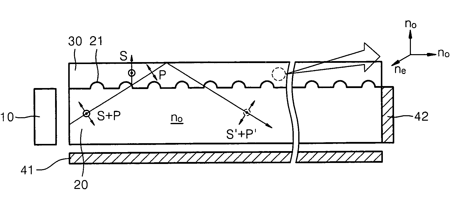
[0026]FIG. 1 is a cross-sectional view of an illumination system having a micro lens array structure on an interface between a light guide plate and an upper layer according to an exemplary embodiment of the present invention. The illumination system includes a light source 10 on at least one end and a light guide plate 20 through which incident light is transmitted. The illumination system further includes an upper layer 30, which may be a film or coating layer disposed on a top surface of the light guide plate 20.

[0027]The light guide plate 20 is formed of an optically isotropic material whose refractive index of no is consistent and not directionally dependent. The upper layer 30 is formed of an optically anisotropic material whose refractive index varies directionally. In other words, in the direction of the z axis an...


PUM

PropertyMeasurementUnit
refractive indicesaaaaaaaaaa
refractive indexaaaaaaaaaa
optically anisotropicaaaaaaaaaa

Abstract

An illumination system for a flat panel display device includes: a light guide plate made of an optically isotropic material; a light source disposed at a side of the light guide plate; an upper layer disposed on a top surface of the light guide plate and made of an optically anisotropic material; and a polarization selection emitting structure which is disposed at an interface of the light guide plate and the upper layer. The upper layer has two different refractive indices and one of the two refractive indices is the same as a refractive index of the light guide plate. In the polarization selection emitting structure differently polarized light is differently refracted, reflected, diffracted, or scattered based on polarization direction.

Description

CROSS-REFERENCE TO RELATED PATENT APPLICATIONS[0001]This application claims the benefit of Korean Patent Application No. 10-2005-0079127, filed on Aug. 27, 2005 in the Korean Intellectual Property Office, the disclosure of which is incorporated herein in its entirety by reference.BACKGROUND OF THE INVENTION[0002]1. Field of the Invention[0003]Apparatuses consistent with the present invention relate to an illumination system for a flat panel display device in which light, incident on a light guide plate from a light source disposed at a side of the illumination system, is polarized to be emitted to a flat panel display device.[0004]2. Description of the Related Art[0005]Typical flat panel display devices include light emission type flat panel display devices and light receiving type flat panel display devices. Liquid crystal displays (LCDs), which are a type of flat panel displays, are light receiving type displays that are not self-luminescent but which form an image using incident ...

Claims


Application Information

Patent Timeline
Patent Type & Authority Patents(United States)
IPC IPC(8): G02F1/1335F21V7/04G02B6/10
CPCG02B6/0056G02F1/13362Y10S385/901G02F1/1335
Inventor LEE, MOON-GYUNAM, SEUNG-HOHWANG, SEONG-MOKIM, YOUNG-CHANWEE, DONG-HOKIM, KYUNG-YEUP
Owner SAMSUNG DISPLAY CO LTD
Why Eureka
Try Eureka