Eureka AIR delivers breakthrough ideas for toughest innovation challenges, trusted by R&D personnel around the world.

Method for structuring a gear assembly housing

Active Publication Date: 2010-03-02
DYNATRAC PROD LLC
View PDF11 Cites 10 Cited by
  • Summary
  • Abstract
  • Description
  • Claims
  • Application Information

AI Technical Summary

Benefits of technology

[0004]The present invention is directed to structures designed to house gear assemblies of land mobile vehicles. The gear housing may have an upper housing portion and a lower housing portion. The lower housing portion may have a wall reference position below a lowest surface structure of a gear assembly wherein a wall of smooth, generally non-planar surfaces may be positioned below a gear assembly centerline with an interior surface at the wall reference position adjacent the lowest surface structure with sufficient separation to avoid contact between the gear housing and the gear assembly. This separation between the gear housing and the gear assembly may allow for the tolerances and material temperature variations of the structural elements. The wall may have at least one concave curved segment to position the wall adjacent to a contour of outer surface structures of the gear assembly, but not contacting the gear assembly. An upper housing portion may be attached to the lower housing portion to enclose the gear assembly.

Problems solved by technology

However, where terrain clearance is an issue, these shapes may not maximize the clearance, for example, for use with on / off road vehicles such as wheeled, tracked and like land mobile vehicles.

Method used


Image

  • Method for structuring a gear assembly housing
  • Method for structuring a gear assembly housing
  • Method for structuring a gear assembly housing

Examples


Embodiment Construction

[0010]The following detailed description represents the best currently contemplated modes for carrying out the invention. The description is not to be taken in a limiting sense, but is made merely for the purpose of illustrating the general principles of the invention.

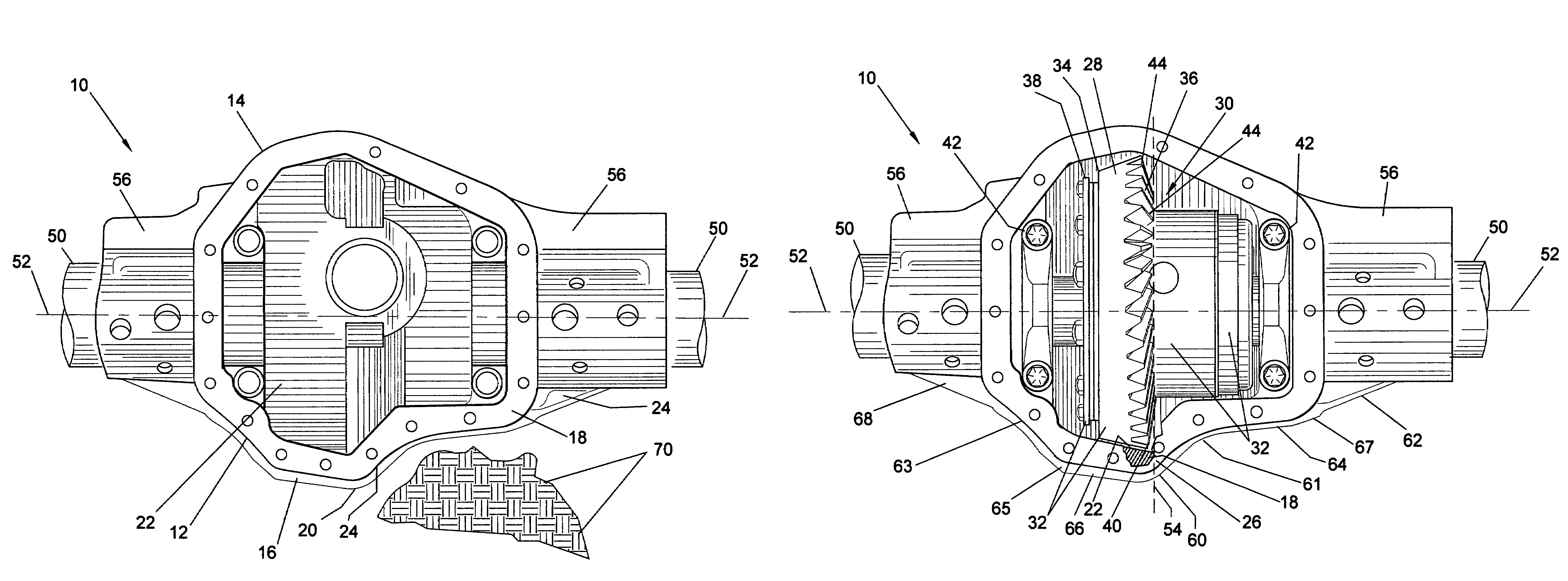
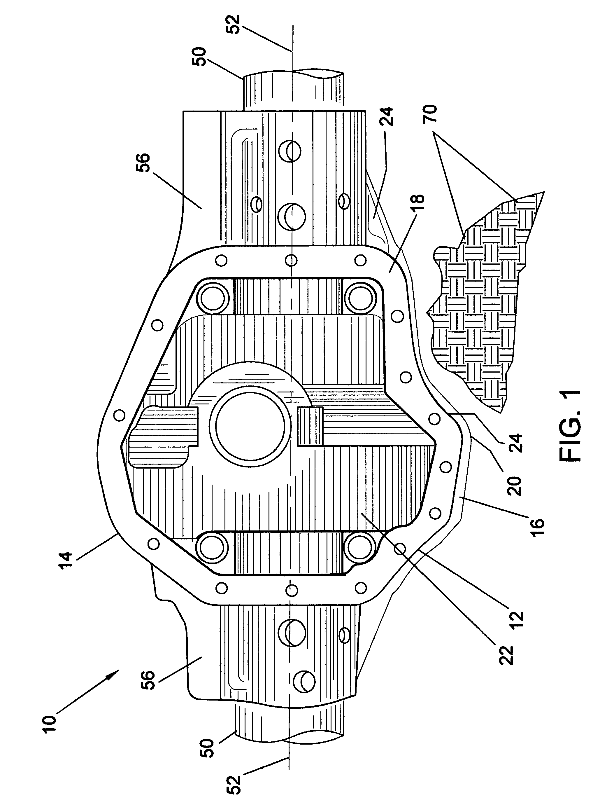
[0011]Referring to FIG. 1, a rear axle differential gear housing 10 may be attached to a rear axle assembly and supporting drive apparatus (not shown). The gear housing 10 as part of a wheeled vehicle may travel on irregular terrain that may have large vertical variation characteristics such as rocks 70 or the ground. Often the vertical clearance between the terrain and the vehicle is defined by the gear housing 10 as it may protrude below the axle assembly 50. Any reduction in the portion of the gear housing 10 structure or exterior surface 24 protruding below the axle assembly 50 bottom surface may enhance the mobility of the vehicle.

[0012]The gear housing 10 may have a contoured lower housing portion 12 structure be...


PUM

PropertyMeasurementUnit
Diameteraaaaaaaaaa
Distanceaaaaaaaaaa
Distanceaaaaaaaaaa

Abstract

A method for structuring a gear assembly housing may include: identifying the lowest surface structure of ring gear teeth top lands; forming a lower gear housing portion having a wall positioned below a gear assembly centerline; shaping the wall relative to an axis of an axle to form: a convex curved wall segment adjacent the lowest surface structure joined to a first concave curved wall segment that is joined to a generally linear wall segment; a first transition wall segment that is joined to the generally linear wall segment; a ring gear wall segment of generally linear form joined to the convex curved wall segment; the ring gear wall segment joined to a second concave curved wall segment that transitions to a second transition wall segment; and attaching an upper housing portion.

Description

[0001]This is a continuation-in-part application of U.S. patent application Ser. No. 10 / 165,487 filed on Jun. 7, 2002. U.S. patent application Ser. No. 10 / 165,487 is now abandoned.BACKGROUND OF THE INVENTION[0002]This invention relates to housings for axle gear mechanisms for land mobile vehicles. The improved differential gear axle housing is structured to maximize the clearance between the bottom of the housing and the terrain over which the mobile vehicle may travel.[0003]Gear axle housings have generally been structured in shapes approximating spheres, ovals or egg shapes and the like geometric three-dimensional structures. This may provide strength and ease of manufacturer for such housings. However, where terrain clearance is an issue, these shapes may not maximize the clearance, for example, for use with on / off road vehicles such as wheeled, tracked and like land mobile vehicles.SUMMARY OF THE INVENTION[0004]The present invention is directed to structures designed to house ge...

Claims


Application Information

Patent Timeline
IPC IPC(8): B23P15/14
CPCF16H57/037F16H48/08F16H2048/382F16H2048/385F16H2057/02043Y10T29/49462Y10T29/49696Y10T29/49464Y10T74/2186Y10T74/2188Y10T29/49465F16H2057/02086
Inventor MCGEAN, JIM
Owner DYNATRAC PROD LLC
Why Eureka
Eureka Blog
Learn More