Mounting configuration for a brake control device on a motorcycle, and motorcycle including same

a technology for controlling devices and motorcycles, applied in the direction of braking systems, cycle brakes, cycle equipments, etc., can solve the problems of large and heavy parts of the ABS unit, and achieve the effect of light weight and minimal engine influence on the brake control devi

Active Publication Date: 2010-03-02
HONDA MOTOR CO LTD
View PDF11 Cites 22 Cited by
  • Summary
  • Abstract
  • Description
  • Claims
  • Application Information

AI Technical Summary

Benefits of technology

[0010]Accordingly, the brake control device is mounted on the motorcycle without adding a large change to design of the basic model of the vehicle. Further, the brake control device, which is a heavy object, can be arranged at a comparatively low position on the frame, thus contributing to the lowering of the center of gravity of the vehicle.
[0024]According to the eighth aspect of the invention, by providing the joining portion in the vicinity of the center of gravity, which becomes the center of vibration of the engine, and by arranging the brake control device so as to be situated proximate the center of gravity, it is possible to minimize an influence of engine on the brake control device. Accordingly, a mount between the brake control device and the engine and the mount structure between the engine and a frame can be made small and light in weight.

Problems solved by technology

The ABS unit is a relatively large and heavy part.
That is, in adopting the chain drive structure as a drive means, when the brake control device is arranged below a chain line, the brake control device interferes with a chain and sprocket wheels and hence, it is necessary to offset the chain line and the brake control device in the right and left directions respectively.

Method used


Image

  • Mounting configuration for a brake control device on a motorcycle, and motorcycle including same
  • Mounting configuration for a brake control device on a motorcycle, and motorcycle including same
  • Mounting configuration for a brake control device on a motorcycle, and motorcycle including same

Examples


second embodiment

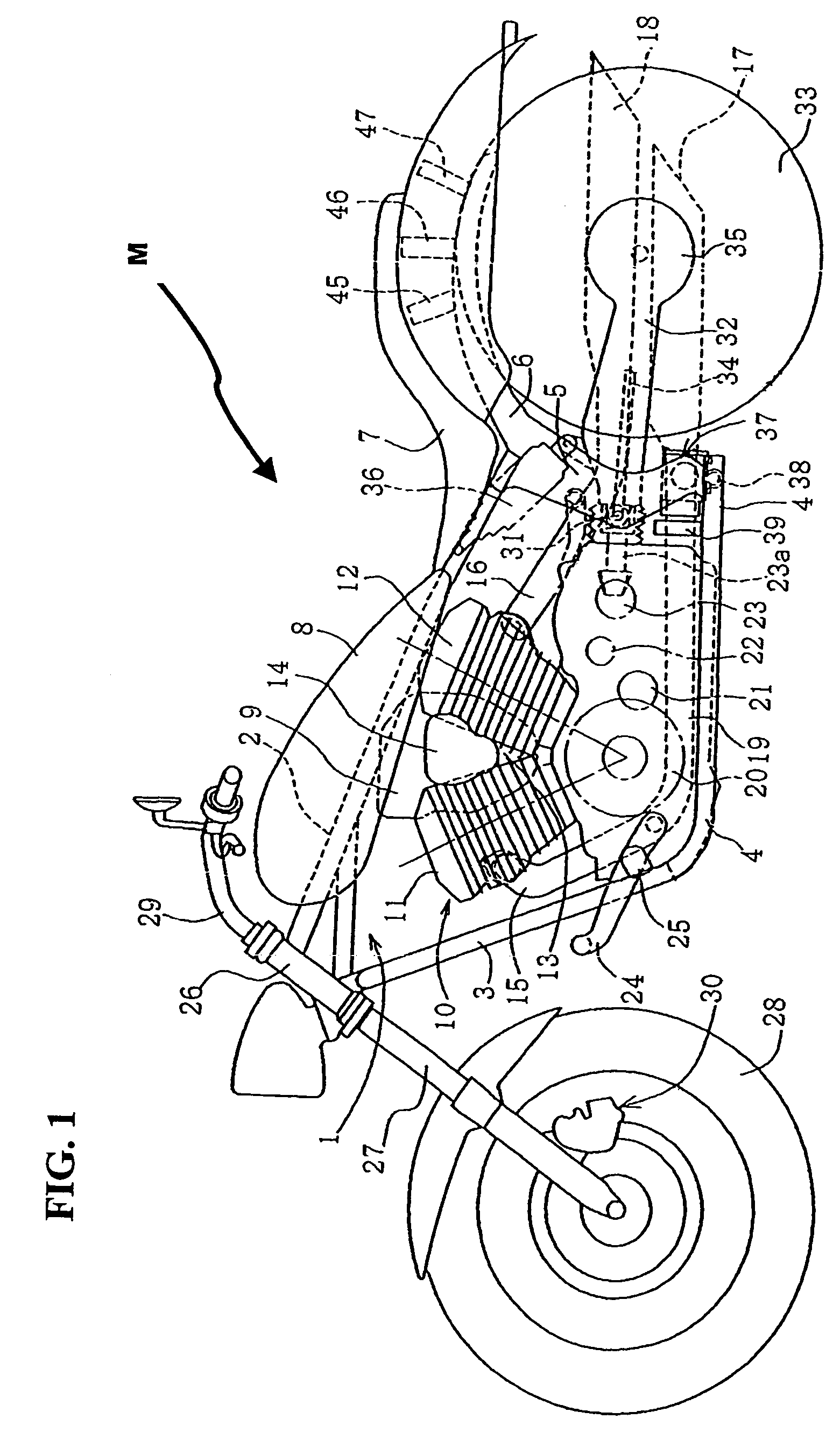
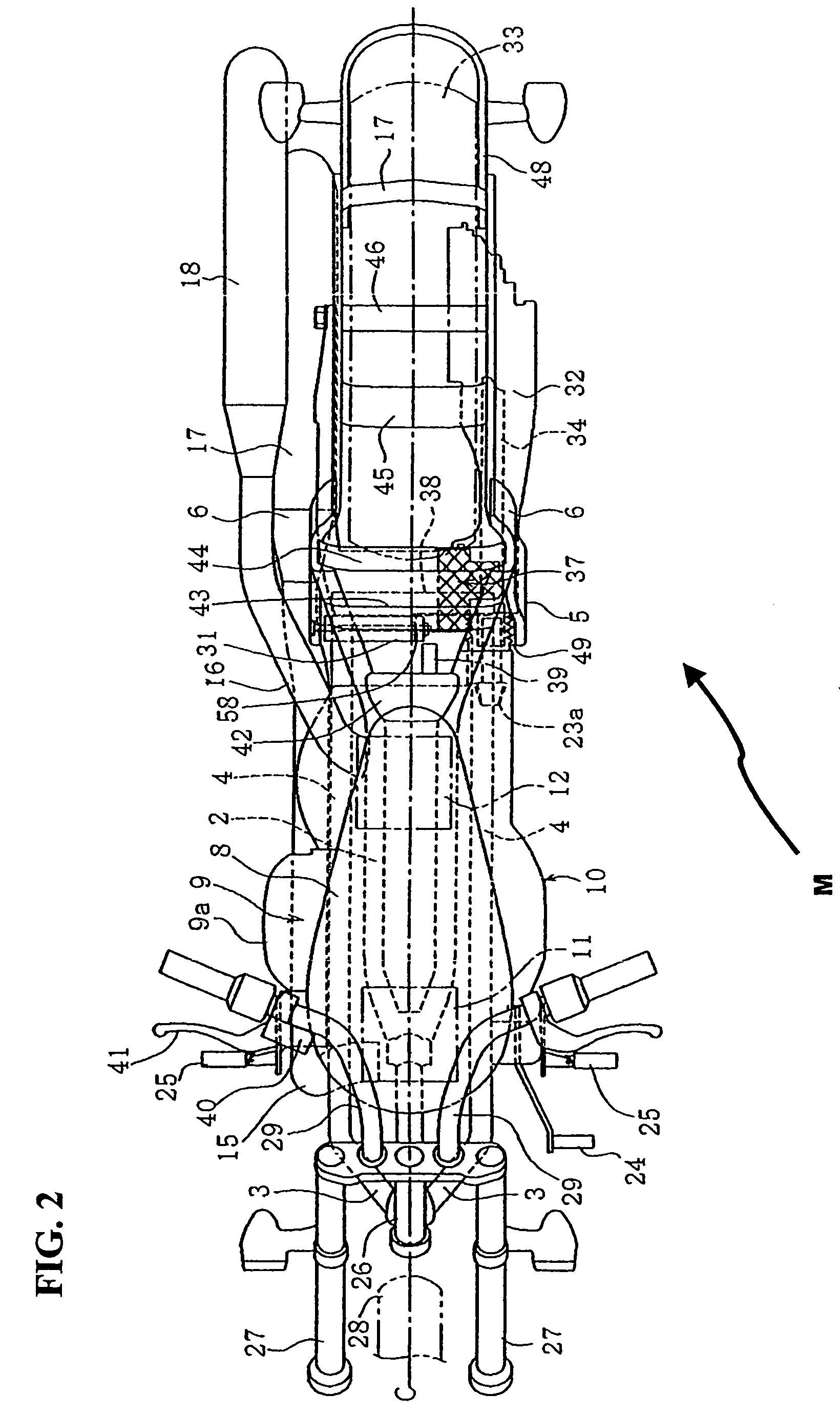
[0066]Next, the invention is presented in which an ABS unit 37 is arranged on an engine side. Here, a vehicle body to which the ABS unit 37 is applied is the same as the vehicle body shown in FIG. 1 and FIG. 2.

[0067]FIG. 6 is a side plan view of the motorcycle M with an alternative mounting configuration of the brake control unit 37, according to a second embodiment hereof. In this embodiment, the ABS unit 37 is arranged on a side of a lower portion of in the V-shaped space 13 formed between the front cylinder 11 and the back cylinder 12. The ABS unit 37 has a periphery thereof, excluding the respective cylinder side, covered with a unit cover 60. The unit cover 60 is described in detail later.

[0068]The ABS unit 37 is situated on the engine such that, as viewed in a side view shown in the drawing, a maximum side projecting point P1 of the ABS unit 37 (corresponding to a distal end portion of the cylindrical portion 56 in this embodiment) is arranged in front of a straight line L whi...

first embodiment

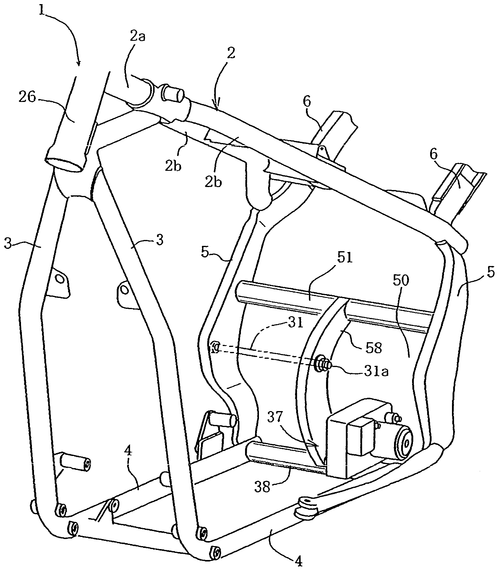
[0075]The mounting configuration of the ABS unit 37 will now be described. A rear end surface of a quadrangular body portion 55, as viewed in a side view, is supported at one position on a vertical stay 66 by way of a vibration-dampening rubber grommet 53. In addition, a lower surface of the body portion 55 is supported at two positions on a horizontal stay 67 in the same manner by way of vibration-dampening rubber grommets 53. The vibration-dampening rubber grommets 53 are substantially similar to the vibration control rubber grommets used in the above-mentioned first embodiment, and are fastened to the body portion 55 and the respective stays 66, 67 respectively using bolts54.

[0076]The vertical stay 66 and the horizontal stay 67 are, respectively, integrally formed with an approximately triangular mounting bracket 68, and the mounting bracket 68 is fastened to a side surface of a lower portion of the rear cylinder 12 and also to a side surface of an upper portion of a crankcase 19...


PUM


Abstract

A mounting configuration is provided for mounting an ABS unit on a base model motorcycle which permits a relatively large-sized and heavy ABS unit to be easily mounted on a vehicle body frame. A V-shaped engine is longitudinally mounted on the frame, and a rear wheel is supported on a rear swing arm which is pivotally supported on the frame by a pivot shaft, the rear wheel driven via a drive shaft. An ABS unit is arranged on one side of the vehicle body in a space below and to one side of the pivot shaft so as to avoid interference with the rear swing arm or the like, thus it is possible to easily mount the ABS unit on a base model. Further, by arranging exhaust pipe system parts on another side of the vehicle body, it is possible to obtain a proper lateral balance of the vehicle body.

Description

CROSS-REFERENCE TO RELATED APPLICATIONS[0001]The present invention claims priority under 35 USC 119 based on Japanese patent application No. 2005-380494, filed on Dec. 28, 2005. The subject matter of this priority document, including specification, drawings, and claims, is incorporated by reference herein.BACKGROUND OF THE INVENTION[0002]1. Field of the Invention[0003]The present invention relates a brake control device for a motorcycle, and more particularly, to a mounting configuration of an anti-lock brake control unit (hereinafter referred to as ABS unit) on a motorcycle frame.[0004]2. Description of the Background Art[0005]An ABS unit is a known device which automatically controls hydraulic pressure of a hydraulic brake mechanism, in order to prevent a wheel from being locked during vehicle braking. The ABS unit is also referred to as an ABS modulator, and is primarily made up of an integral body including a hydraulic circuit, a pump and a valve. The ABS unit is a relatively la...

Claims


Application Information

Patent Timeline
Patent Type & Authority Patents(United States)
IPC IPC(8): B62D61/02B60T8/34B62J99/00B62J23/00B62L3/00B62L3/04B62M7/02B62M17/00
CPCB60T8/3685B62K11/04B62K19/30
Inventor HASEGAWA, YOSUKE
Owner HONDA MOTOR CO LTD
Why Eureka
Try Eureka