Supercharge Your Innovation With Domain-Expert AI Agents!

Objective holder for camera module

a technology for objects and camera modules, applied in the field of object holders, can solve the problems of poor image quality, contribute to the bulkiness of the object holders, and bulky objects

Inactive Publication Date: 2010-03-02
POLIGHT TECH LTD
View PDF12 Cites 3 Cited by
  • Summary
  • Abstract
  • Description
  • Claims
  • Application Information

AI Technical Summary

Benefits of technology

The present invention is a holder for a camera that attaches to a circuit board with a sensor and other components. The holder has a lens and walls that surround the sensor. A transparent cover is placed between the lens and the sensor. The holder is attached to the circuit board with adhesive. The circuit board contacts the walls. The holder has a sealed chamber for outgassing and a sealing material after the adhesive is heated. The technical effect of this invention is to provide a reliable and efficient attachment of a camera to a circuit board with a sensor and other components.

Problems solved by technology

Therefore, the objective holder is bulky.
A great deal of gas is given off, raising pressure in the chamber, thus risking offsetting the image sensing IC from the lens module, which may result in poor image quality.
Conventionally, the hole is defined in a peripheral wall of the chamber adjacent to the barrel, which also contributes to the bulkiness of the objective holder.

Method used


Image

  • Objective holder for camera module
  • Objective holder for camera module
  • Objective holder for camera module

Examples


Embodiment Construction

[0017]Embodiments of the present objective holder will now be described in detail below and with reference to the drawings.

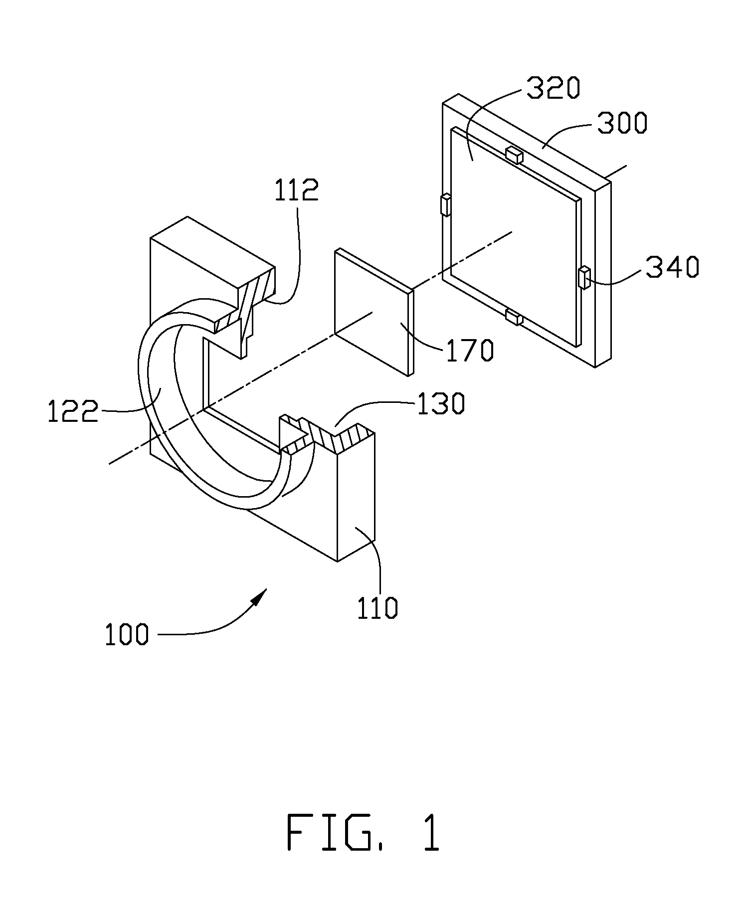
[0018]Referring to FIGS. 1-3, an objective holder 100 in the first embodiment may be engaged with a printed circuit board (PCB) substrate 300. An image sensor 320 and four passive components 340 are arranged on the PCB substrate 300. The passive components 340 surround the image sensor 320. The image sensor 320 may be a charge coupled device (CCD) image sensor or a complementary metal oxide semiconductor (CMOS) image sensor. The passive components 340 may be capacitors, inductors, or resistors.

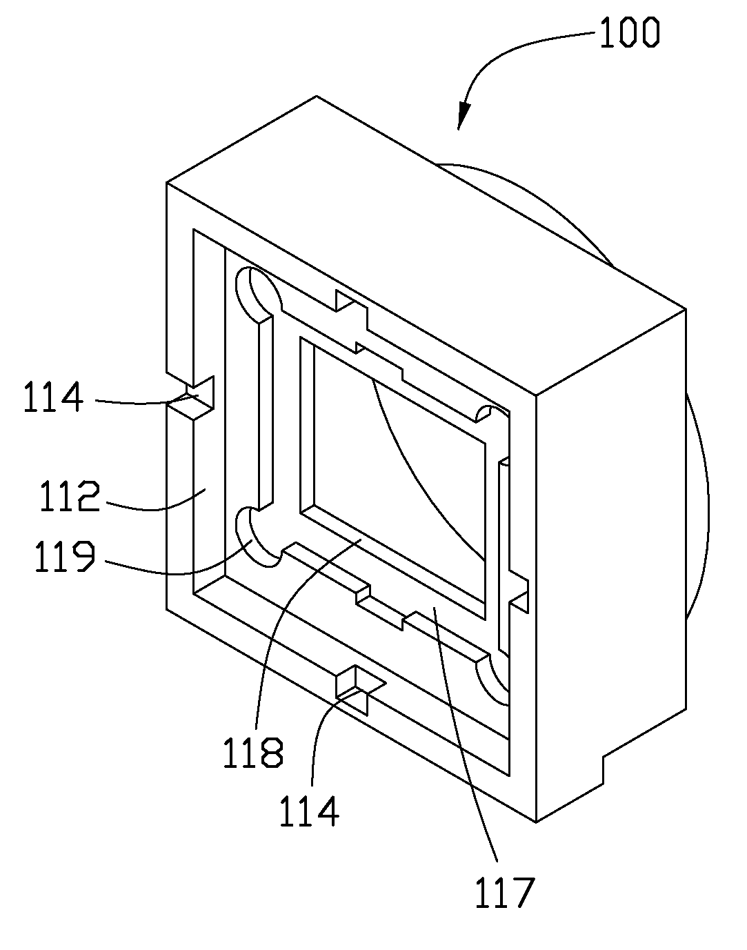
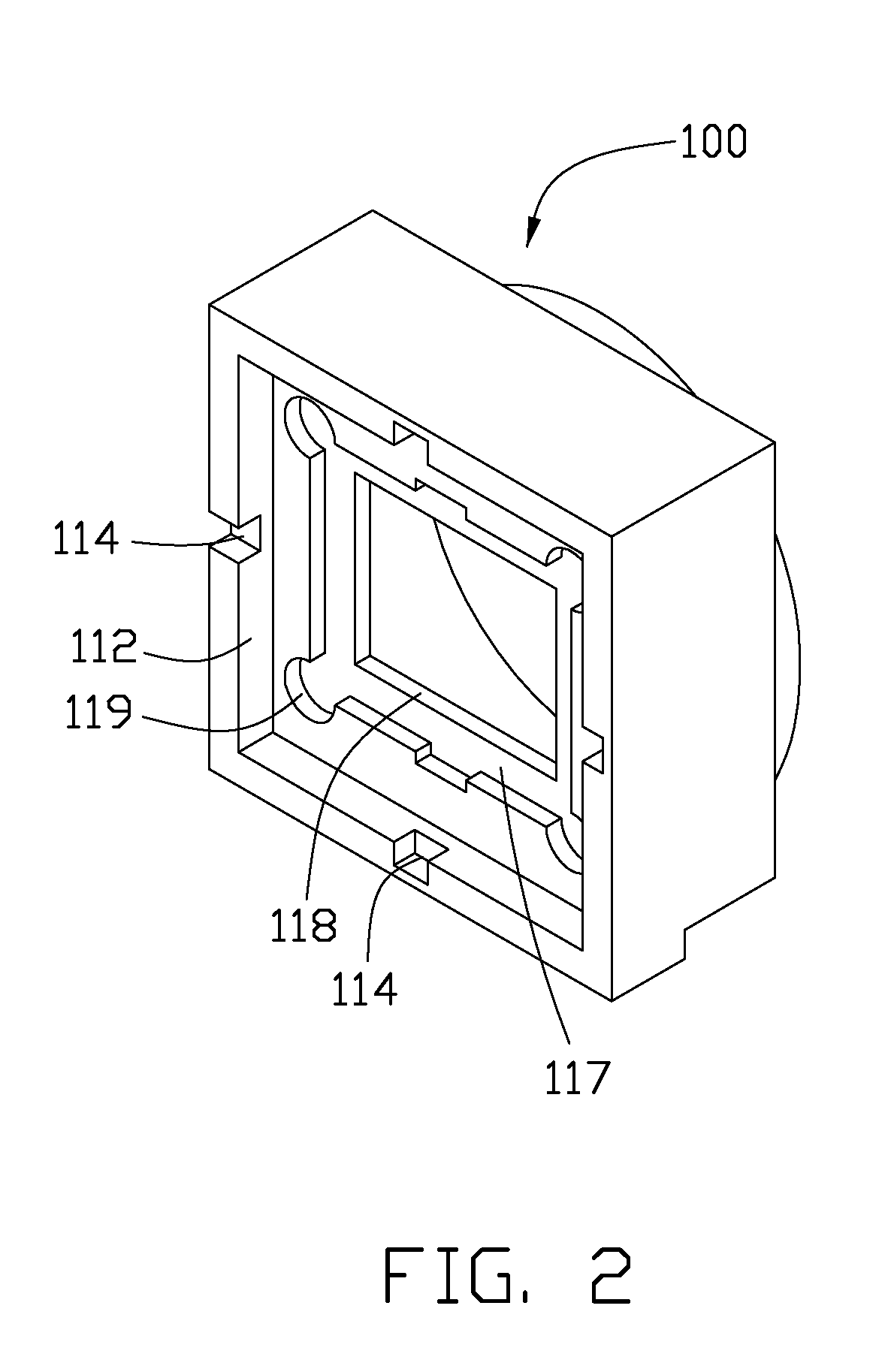
[0019]The objective holder 100 comprises a base 110, a lens barrel 122, and four walls 112. The lens barrel 122 and the four walls 112 oppositely extend from the base 110. The lens barrel 122 is for receiving a lens module (not shown). The lens module (not shown) can be secured in the lens barrel 122 by any conventional means. The walls 112 are contiguous and cooperatively...


PUM


Abstract

An exemplary objective holder engages with a PCB substrate having an image sensor and several passive components arranged thereon. The passive components surround the image sensor. The objective includes a lens barrel extending from a side of a base, and a plurality of walls extending from an opposite side of the base. The walls enclose a chamber thereamong for receiving the image sensor and define notches therein for receiving the passive components therein. A transparent cover is received in the objective holder between the lens barrel and the chamber. An adhesive is used to connect the objective holder to the PCB substrate. The PCB substrate is rested on the walls. At least one of the notches communicates the chamber to an exterior for outgassing and is sealed by a mass of sealing material after a heating process of the adhesive.

Description

CROSS-REFERENCE OF RELATED APPLICATION[0001]This application is related to a co-pending U.S. patent application Ser. No. 11 / 947,081, entitled “OBJECTIVE HOLDER FOR CAMERA MODULE”, which was filed on Nov. 29, 2007 and assigned to the same assignee. The disclosure of the above identified application is incorporated herein by reference.BACKGROUND[0002]1. Technical Field[0003]The present invention relates to objective holders and, particularly, to an objective holder for a camera module having a compact configuration.[0004]2. Description of Related Art[0005]In digital cameras, objective holders are in widespread use to support lenses and other components such as image sensors. Another use for objective holders is in some compact imaging apparatus as a cover for imaging components. Typically, a lens holder comprises a lens barrel in a front thereof and defines a chamber in a rear thereof for receiving an image sensing IC and passive components therein. The image sensing IC and the passiv...

Claims


Application Information

Patent Timeline
Patent Type & Authority Patents(United States)
IPC IPC(8): G03B17/00G03B17/02G02B7/02
CPCG03B17/00H04N5/2254H04N5/2257H04N23/50H04N23/57
Inventor CHENG, SU-JENLAI, WEN-CHINGCHEN, WEN-CHANG
Owner POLIGHT TECH LTD
Features
  • R&D
  • Intellectual Property
  • Life Sciences
  • Materials
  • Tech Scout
  • Unparalleled Data Quality
  • Higher Quality Content
  • 60% Fewer Hallucinations
Learn More