
Wide-band directional coupler

a directional coupler and wideband technology, applied in the field of couplers, can solve the problems of large insertion loss, adversely affecting the optimization of the transmission chain operation, and the coupling is very sensitive to the frequency of the transmitted signal

Inactive Publication Date: 2010-03-02
STMICROELECTRONICS SRL
View PDF6 Cites 11 Cited by
  • Summary
  • Abstract
  • Description
  • Claims
  • Application Information

AI Technical Summary

Benefits of technology

This configuration stabilizes coupling across a wide frequency band, reduces coupling factor ripple, and maintains high directionality, achieving improved performance by minimizing insertion losses and enhancing robustness against electrostatic discharges without additional protection.

Problems solved by technology

The longer the lines, the greater the insertion losses.
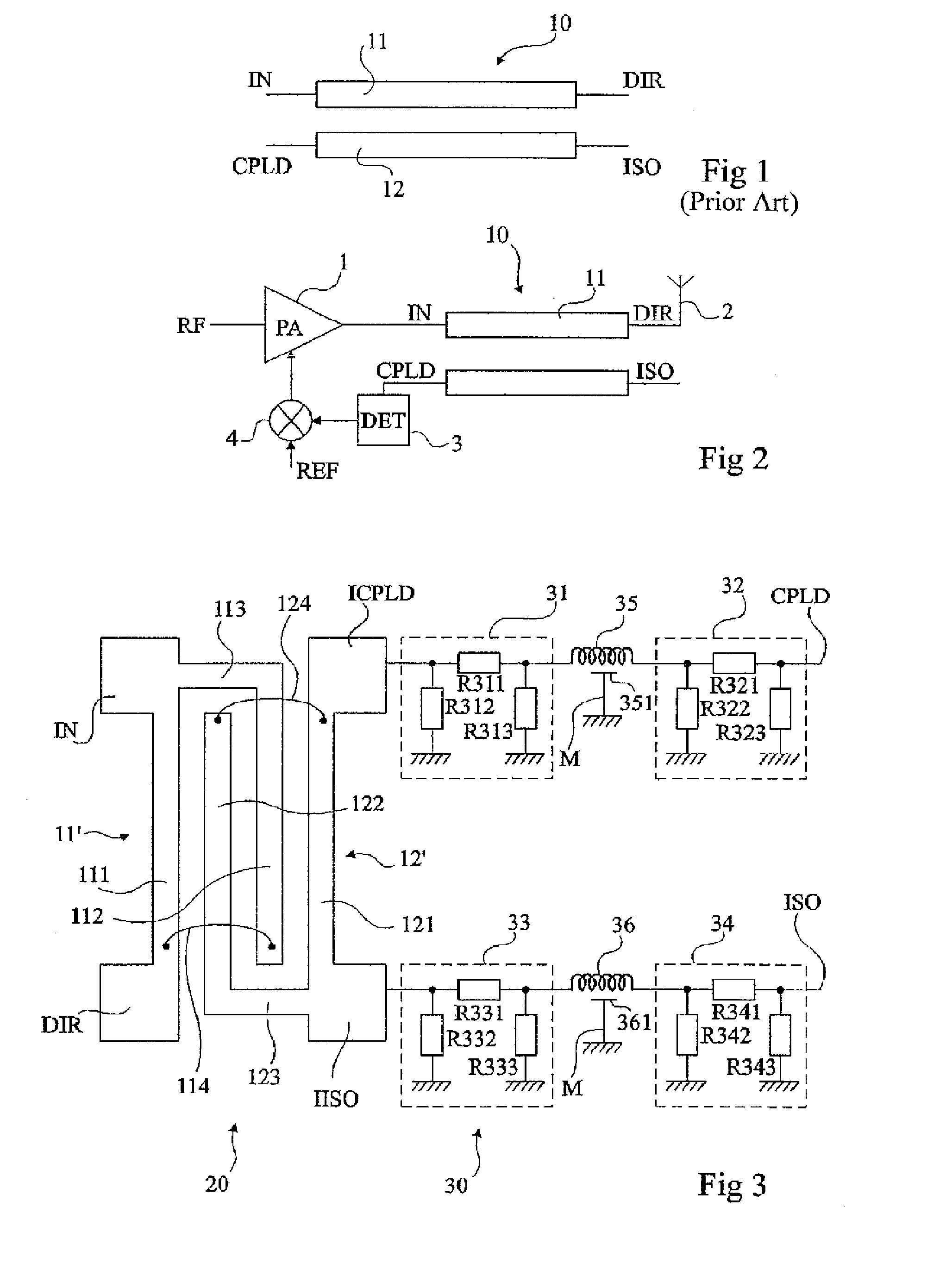
A disadvantage of couplers of the type illustrated in FIG. 1 is that the coupling is very sensitive to the frequency of the transmitted signal.
Indeed, too high a variation of the coupling within the same operating frequency band (for example, GSM or DCS) adversely affects the optimization of the transmission chain operation.
A disadvantage is that, in frequency bands aimed at by the present invention, the values of the capacitive elements are so low that they become close to the values of the stray capacitances of the structure, which makes the coupler difficult to form.

Method used


Image

  • Wide-band directional coupler
  • Wide-band directional coupler
  • Wide-band directional coupler

Examples


Embodiment Construction

[0042]The same elements have been designated with the same reference numerals in the different drawings which have been drawn out of scale. For clarity, only those elements which are useful to the understanding of the present invention have been shown in the drawings and will be described hereafter. In particular, the signals crossing the coupler as well as what exploitation is made of the measurements by the coupled line have not been detailed, the present invention being compatible with any conventional application of such signals.

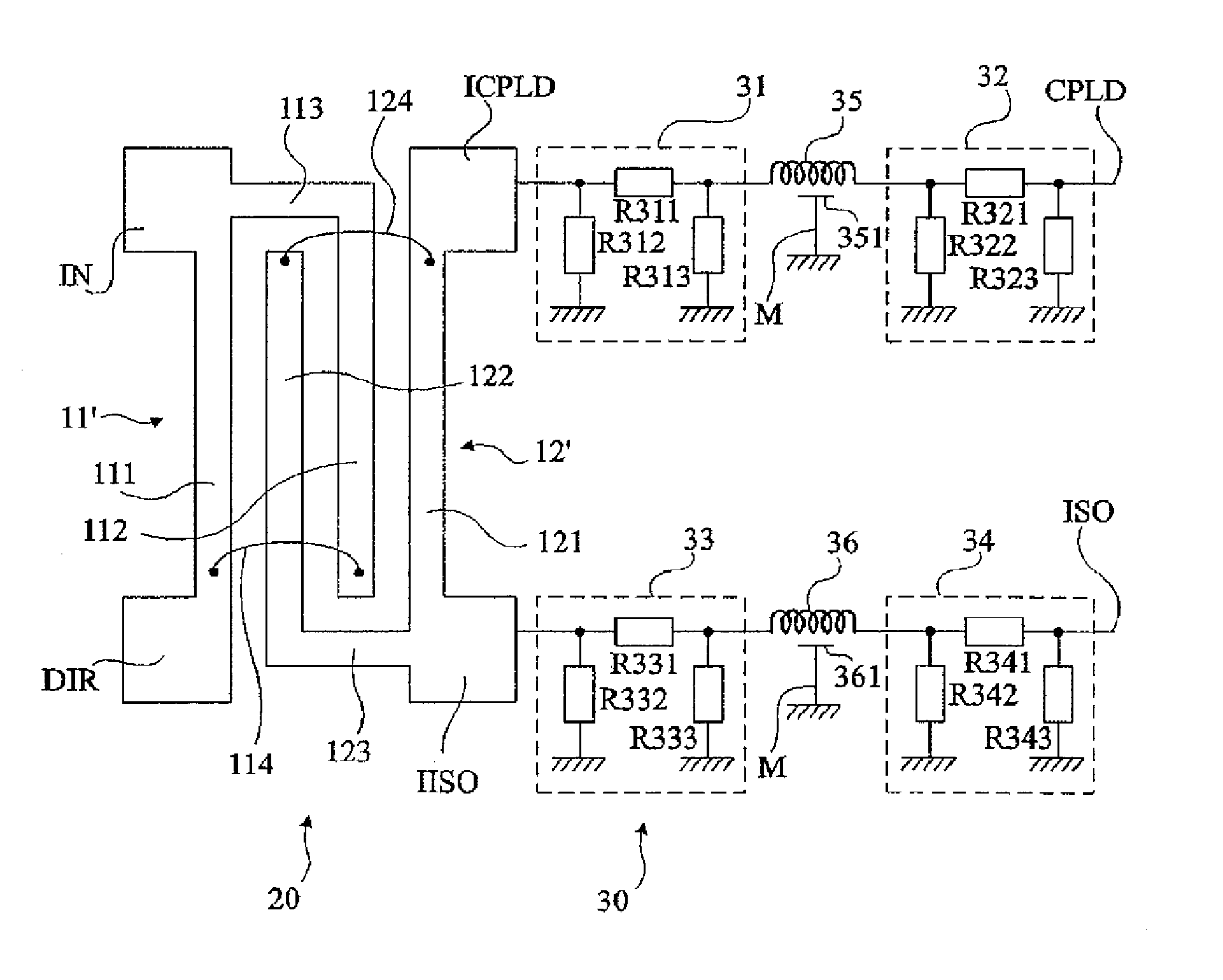
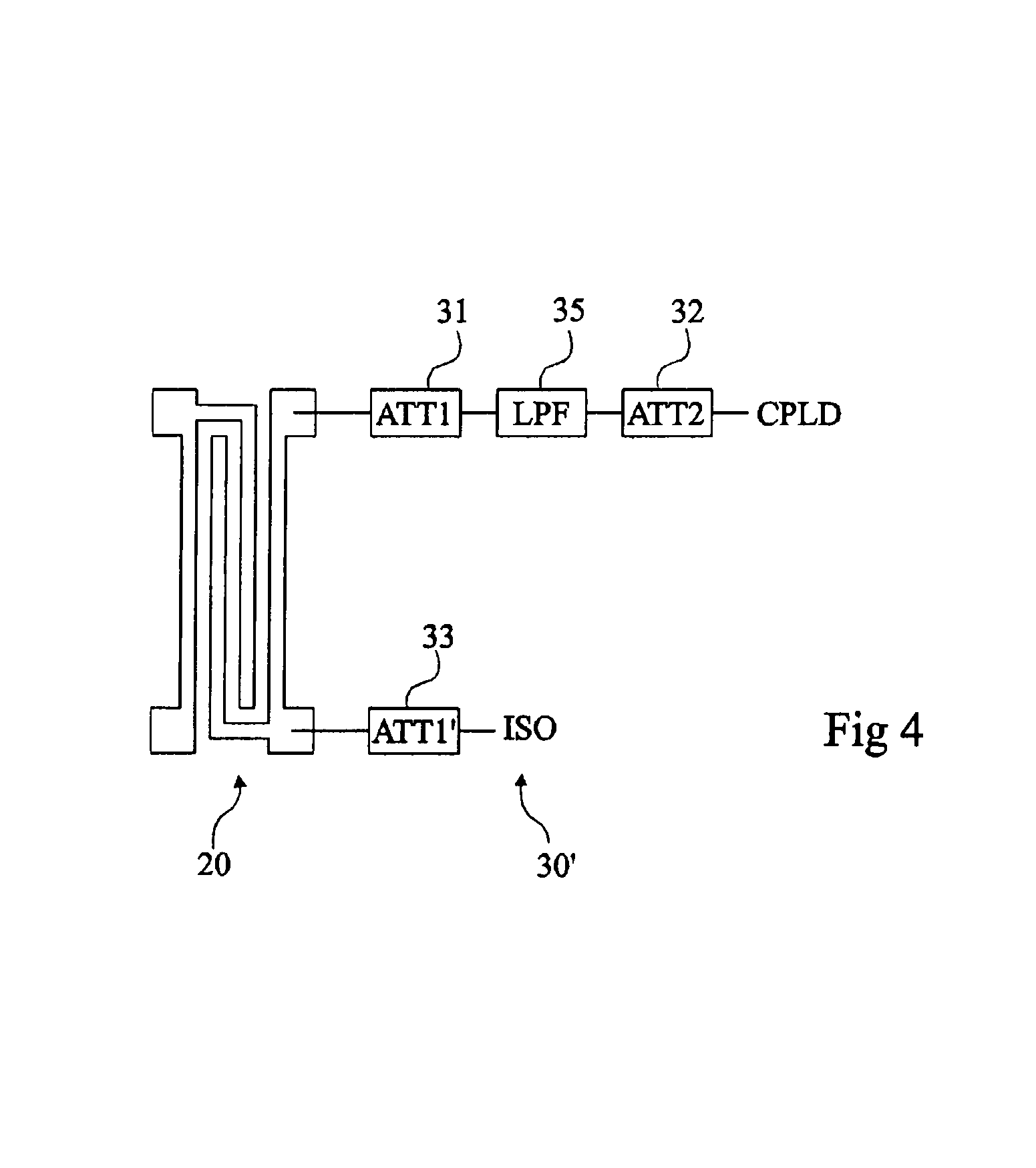
[0043]A feature of an embodiment of the present invention is to combine a structure with distributed lines of Lange structure type with a structure with local elements comprising at least one low-pass filter in series with the secondary line of the distributed structure.

[0044]FIG. 2 shows the diagram of an embodiment of a coupler according to the present invention.

[0045]This coupler comprises a structure 20 with distributed lines associated with a struct...


PUM


Abstract

A directional coupler having a first structure with distributed lines having a first conductive line intended to convey a main signal between two end terminals and having a second conductive line, coupled to the first one, intended to convey a secondary signal proportional to the main signal; and a second structure with local elements including, between a first terminal of the coupler intended to extract the secondary signal and a first end of the second line, two attenuators in series between which is interposed a low-pass filter and, between a second terminal of the coupler and the second end of the second line, at least one attenuator.

Description

BACKGROUND OF THE INVENTION[0001]1. Field of the Invention[0002]The present invention generally relates to the field of couplers which are intended to extract data proportional to a signal carried by a transmission line.[0003]The present invention more specifically relates to couplers formed by means of conductive lines coupled to each other with no contact. Such couplers are called couplers with distributed lines as opposed to couplers with local elements, formed from capacitive and inductive elements.[0004]The present invention more specifically applies to the field of radio-frequency couplers, for example, for radio-communication applications of mobile telephony type.[0005]2. Discussion of the Related Art[0006]FIG. 1 shows a conventional example of a coupler 10 with distributed lines. A main line 11 connects an input access IN to an output access DIR. Line 11 forms the primary of the coupler and is intended to convey the useful signal. A secondary line 12 is arranged parallel to ...

Claims


Application Information

Patent Timeline
Patent Type & Authority Patents(United States)
IPC IPC(8): H01P5/18H01P1/20H01P3/08
CPCH01P5/186
Inventor DUPONT, FRANCOISEZZEDDINE, HILAL
Owner STMICROELECTRONICS SRL
Learn More