
Optical fiber sensor

a fiber optic sensor and optical fiber technology, applied in the field of optical sensors, can solve the problems of metal powder accumulation, low workability of liquid level detecting sensors secured to the fuel gauge insertion port, etc., and achieve the effect of high reliability

Inactive Publication Date: 2010-03-02
MITSUBISHI ELECTRIC CORP
View PDF9 Cites 11 Cited by
  • Summary
  • Abstract
  • Description
  • Claims
  • Application Information

AI Technical Summary

Benefits of technology

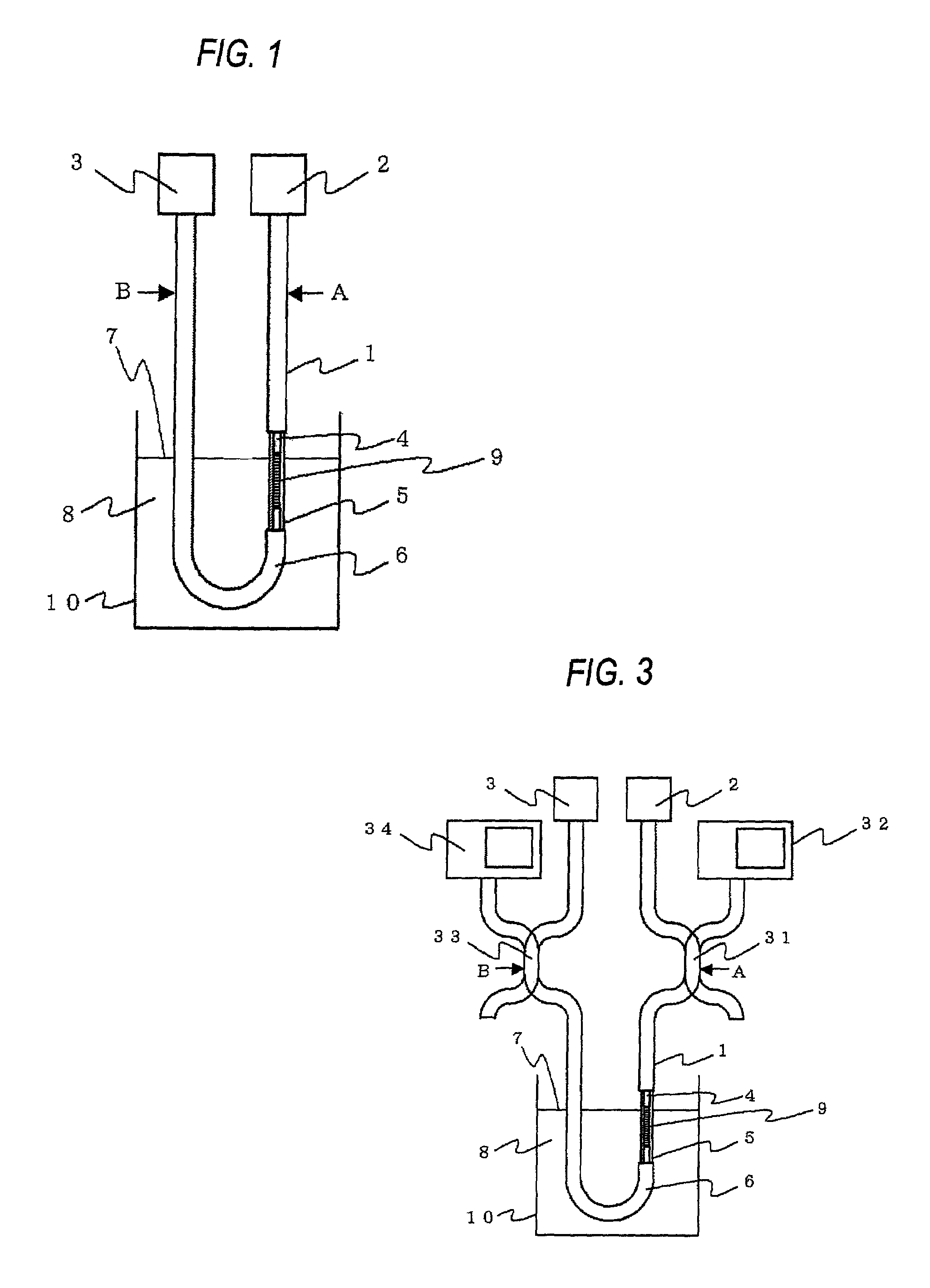
[0014]The optical fiber sensor detects the intensity of the light of the cladding mode transmitted through the area with the grating, the grating being dependent on the refractive index of liquid or gas around the area with granting, and thus the optical fiber sensor can detect the liquid level or detect the property of the liquid. The detection is performed on the basis of the difference in refractive index. Therefore, according to the optical fiber sensor, the liquid level can be detected even when the liquid level varies at all times due to vibration or the like and thus the temperature difference between the gas-phase portion and the liquid-phase portion is moderate. Furthermore, as compared with the method of forming a part of the optical fiber which is greatly narrowed by the fusing-drawing treatment or the like, the intensity of the optical fiber is larger, and it is hardly broken under even a frequently-vibrational environment, so that the liquid level or the property of liquid can be detected with high reliability.

Problems solved by technology

The thus-constructed liquid level detecting sensor has a problem that the workability when the liquid level detecting sensor is secured to the fuel gauge insertion port is low because the bar joined to the float is larger than the diameter of the insertion port of the fuel gauge, and also a problem that metal powder may occur or such a trouble as short-circuit of a variable resistor may occur because there is some sliding portions in the fuel tank.

Method used


Image

  • Optical fiber sensor
  • Optical fiber sensor
  • Optical fiber sensor

Examples


embodiment 1

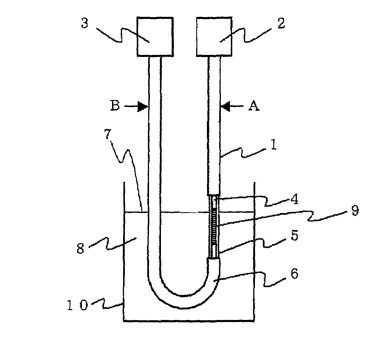
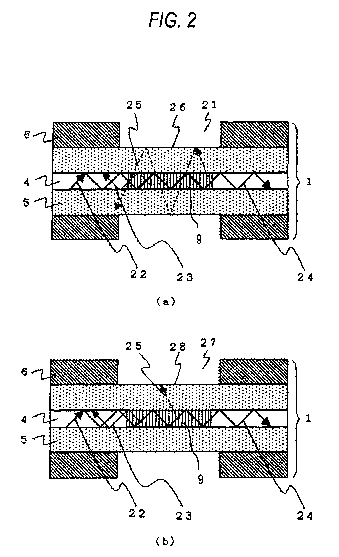
[0063]FIG. 1 is a schematic diagram showing an optical fiber sensor for detecting the liquid level according to an embodiment 1 implementing the present invention. In FIG. 1, a light source 2 is disposed at one end portion of the optical fiber 1, and a light receiving unit 3 is disposed at the other end portion. The optical fiber 1 is equipped with a core 4 through which light emitted from the light source 2 propagates, a clad 5 covering the core 4 so that light is confined in the core 4, and a fiber jacket 6 which covers and protects the above elements. A part of the fiber jacket 6 is removed so that the clad 5 is brought into direct contact with liquid 8 to measure the height of the liquid level 7. The portion from which a part of the fiber jacket 6 is removed is disposed substantially in parallel to the variation direction of the liquid level 7, and a grating 9 is formed at the core 4 corresponding to this portion. The optical fiber 1 is bent in an U-shape in the neighborhood of ...

embodiment 2

[0076]In the embodiment 1, light reaching the light receiving unit also contains light of a large-loss wavelength area which is not relevant to occurrence of the cladding mode and appears at the center of the transmission spectrum. For example, when a photodiode for measuring the intensity of light is used as the light receiving unit, a part of the light intensity to be measured is the light intensity irrelevant to the occurrence of the cladding mode, and thus the variation amount of the light intensity is relatively small due to the loss caused by the cladding mode, so that it would be impossible to enhance the measurement sensitivity. In the embodiment 2, the light of the wavelength area irrelevant to the occurrence of the cladding mode is excluded from the measurement.

[0077]FIG. 7 is a schematic diagram showing a liquid level detecting sensor according to this embodiment. In this embodiment, in the same construction as the embodiment 1, an optical filter 71 is disposed at the por...

embodiment 3

[0079]In the embodiment 2, the light reflected from the optical filter may return to the light source or the grating to induce unnecessary interference, so that it becomes a noise component. In the embodiment 3, the light reflected from the optical filter is prevented from returning to the light source or the grating.

[0080]FIG. 9 is a schematic diagram showing a liquid level detecting optical fiber sensor according to this embodiment. In this embodiment, in the same construction as the embodiment 2, a circulator 91 is disposed between the liquid level 7 and the optical filter 71, and the light reflected from the optical filter 71 is guided to a terminating unit 92 by the circulator 91. The circulator 91 has three ports 91a, 91b and 91c. The terminating unit 92 is a fiber coil of 10 mm or less in diameter. A photodiode for measuring the light intensity is used as the light receiving unit 3, for example.

[0081]The operation of this embodiment will be described. Light emitted from the l...


PUM

PropertyMeasurementUnit
refractive indexaaaaaaaaaa

Abstract

An optical fiber sensor that can detect a liquid level or detect a property of liquid with high reliability even under a frequently vibrational environment. The optical fiber sensor includes an optical fiber that includes a core having an area where a grating is formed and a clad, the optical fiber being disposed so that at least a part of the area with the grating is immersed in liquid, a light source for making light incident to the optical fiber so that a cladding mode light having a wavelength band is generated by the grating, and a light receiving unit for detecting the intensity of light which is incident from the light source to the optical fiber and transmitted through the grating.

Description

TECHNICAL FIELD[0001]The present invention relates to an optical sensor that can be used for a fuel gauge of a fuel tank in a vehicle or the like to detect liquid level or detect the property of liquid.BACKGROUND ART[0002]In a conventional liquid level detecting sensor for a fuel gauge, a bar joined to a float which is displaced in accordance with the height of the liquid level of fuel is rotated in accordance with the height of the liquid surface, and the height of the liquid level is detected on the basis of variation of a resistance value of a variable resistor provided to the movable shaft of the bar (for example, see Patent Document 1). The thus-constructed liquid level detecting sensor has a problem that the workability when the liquid level detecting sensor is secured to the fuel gauge insertion port is low because the bar joined to the float is larger than the diameter of the insertion port of the fuel gauge, and also a problem that metal powder may occur or such a trouble a...

Claims


Application Information

Patent Timeline
Patent Type & Authority Patents(United States)
IPC IPC(8): G02B6/00G01F23/28G01F23/292G01N21/27G01N21/35G01N21/3577G01N21/359G01N21/41
CPCB60K15/077G01F23/292G01F23/2925G01N21/8507B60K2015/03217G01N21/41
Inventor TAKABAYASHI, MASAKAZUYOSHIARA, KIICHISHIMAKURA, YASUHISAMATSUMOTO, SADAYUKIMITANI, TATEKIKANAMARU, SHIGEKIISHII, KAZUSHI
Owner MITSUBISHI ELECTRIC CORP
Learn More