Tissue slicing device

a tissue slicing and tissue technology, applied in the direction of manufacturing tools, transportation and packaging, paper/cardboard containers, etc., can solve the problems of inconvenient cutting of thin slices, inability to cut thick slices, and inconsistent pieces, and achieve the effect of ejecting the cut tissu

Inactive Publication Date: 2010-03-09
GIBERSON RICHARD T +1
View PDF19 Cites 12 Cited by
  • Summary
  • Abstract
  • Description
  • Claims
  • Application Information

AI Technical Summary

Benefits of technology

[0009]Another object is to reliably eject the cut tissue from the slicing device.
[0010]The tissue slicing device is comprised of parallel circular blades coaxially connected to a rotary shaft. The blades are separated from each other by gaps. A guide member is supported by a hinge adjacent the blades. An adjustment screw is positioned behind the guide member. The distance between the guide member and the blades is adjustable by turning the screw. The slicing device includes a tissue carrier which is comprised of a base member

Problems solved by technology

The most commonly used tool is a hand tool such as a scalpel, knife, or razor blade, but it results in pie

Method used


Image

  • Tissue slicing device
  • Tissue slicing device
  • Tissue slicing device

Examples


Embodiment Construction
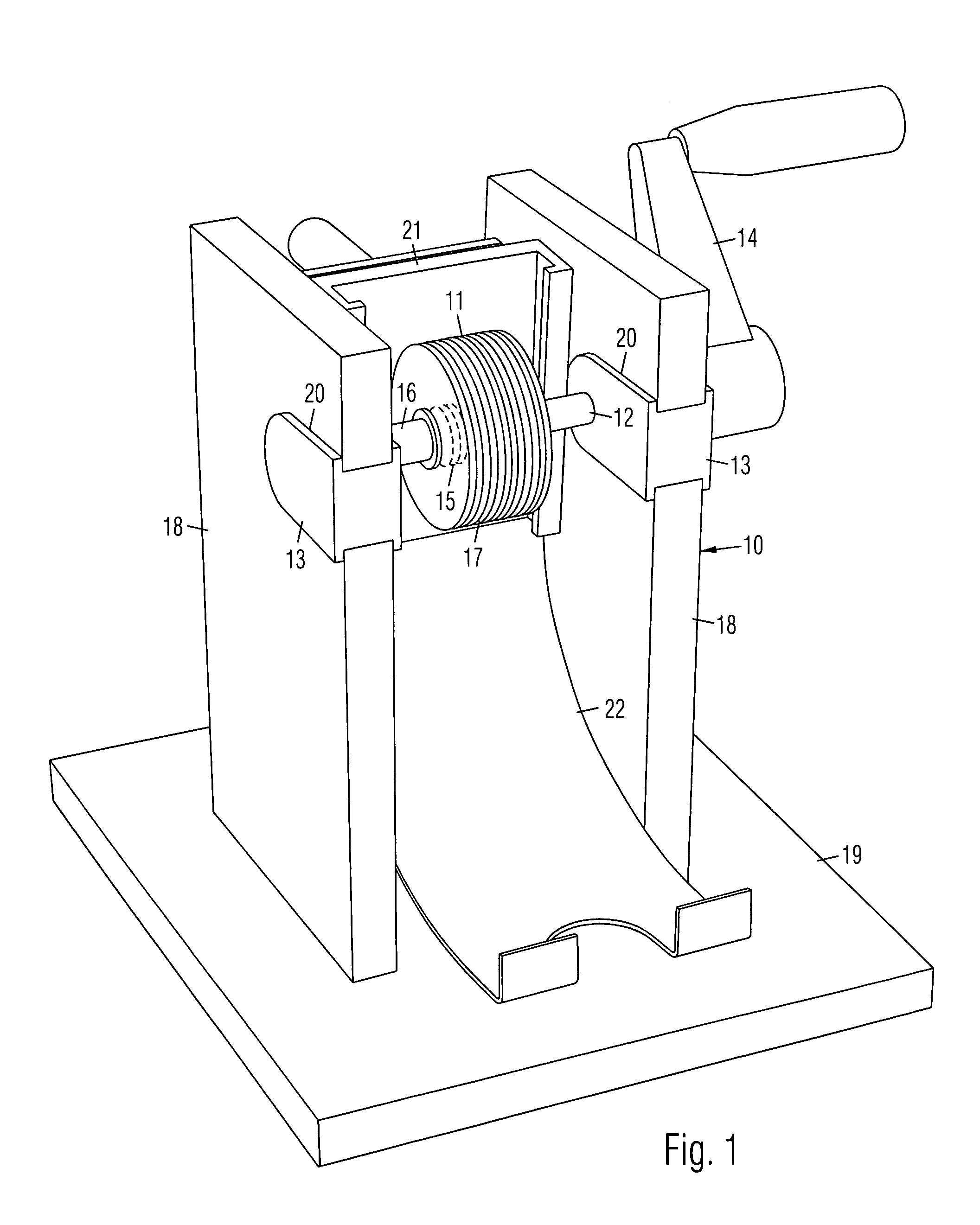
FIG. 1

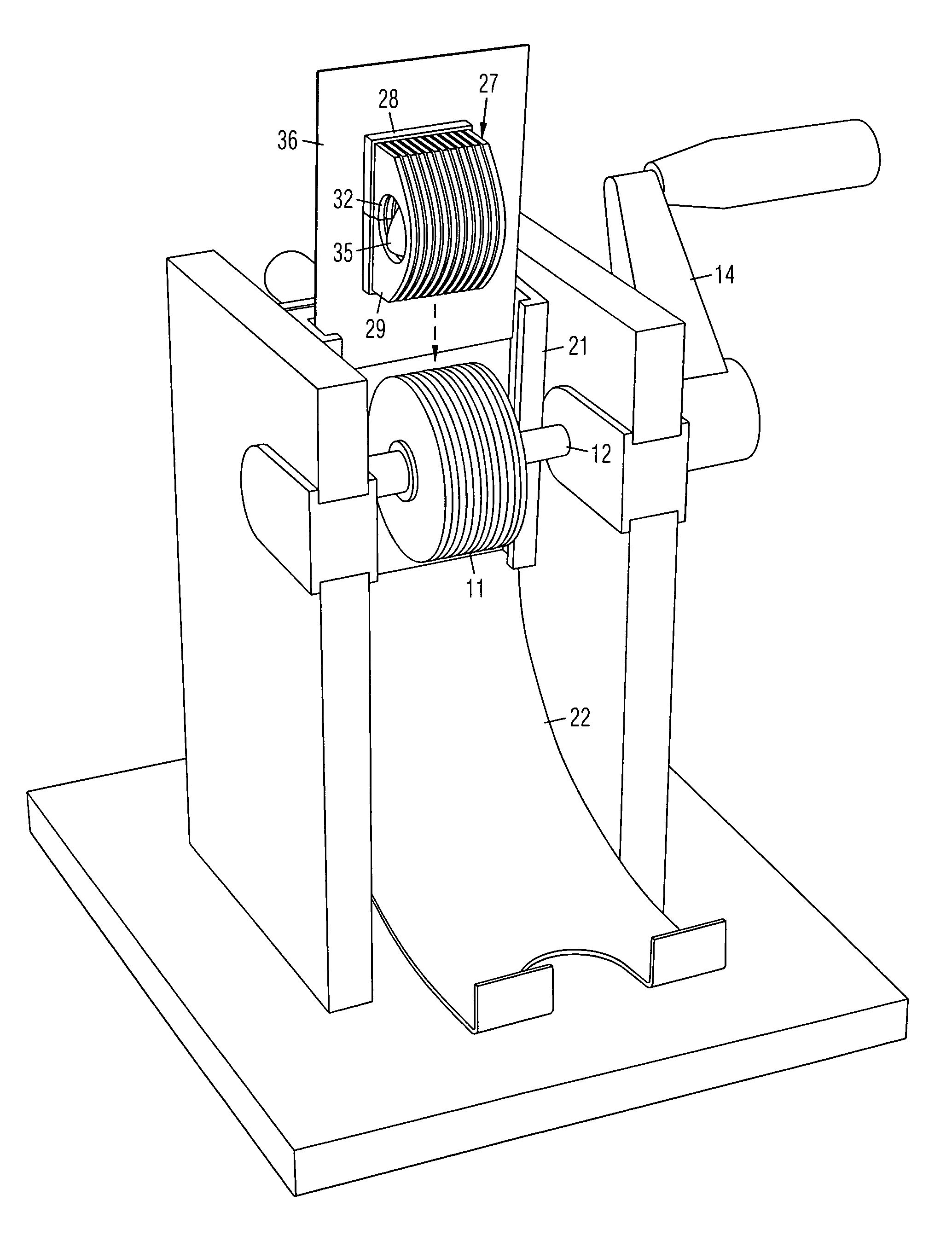
[0018]A preferred embodiment of a tissue slicing device 10 is shown in a front perspective view in FIG. 1. It is comprised of a plurality of parallel circular blades 11 coaxially connected to a rotary shaft 12 supported on bearings 13. A hand crank 14 is attached to shaft 12 for manually turning blades 11, although a motor (not shown) may be attached instead. Blades 11 are axially separated from each other by respective spacers 15 and secured on shaft 12 by a fastener 16. The width of gaps 17 between blades 11 are adjustable by removing fastener 16, removing blades 11 and spacers 15 from shaft 12, and reassembling blades 11 on shaft 12 with spacers of a different thickness.

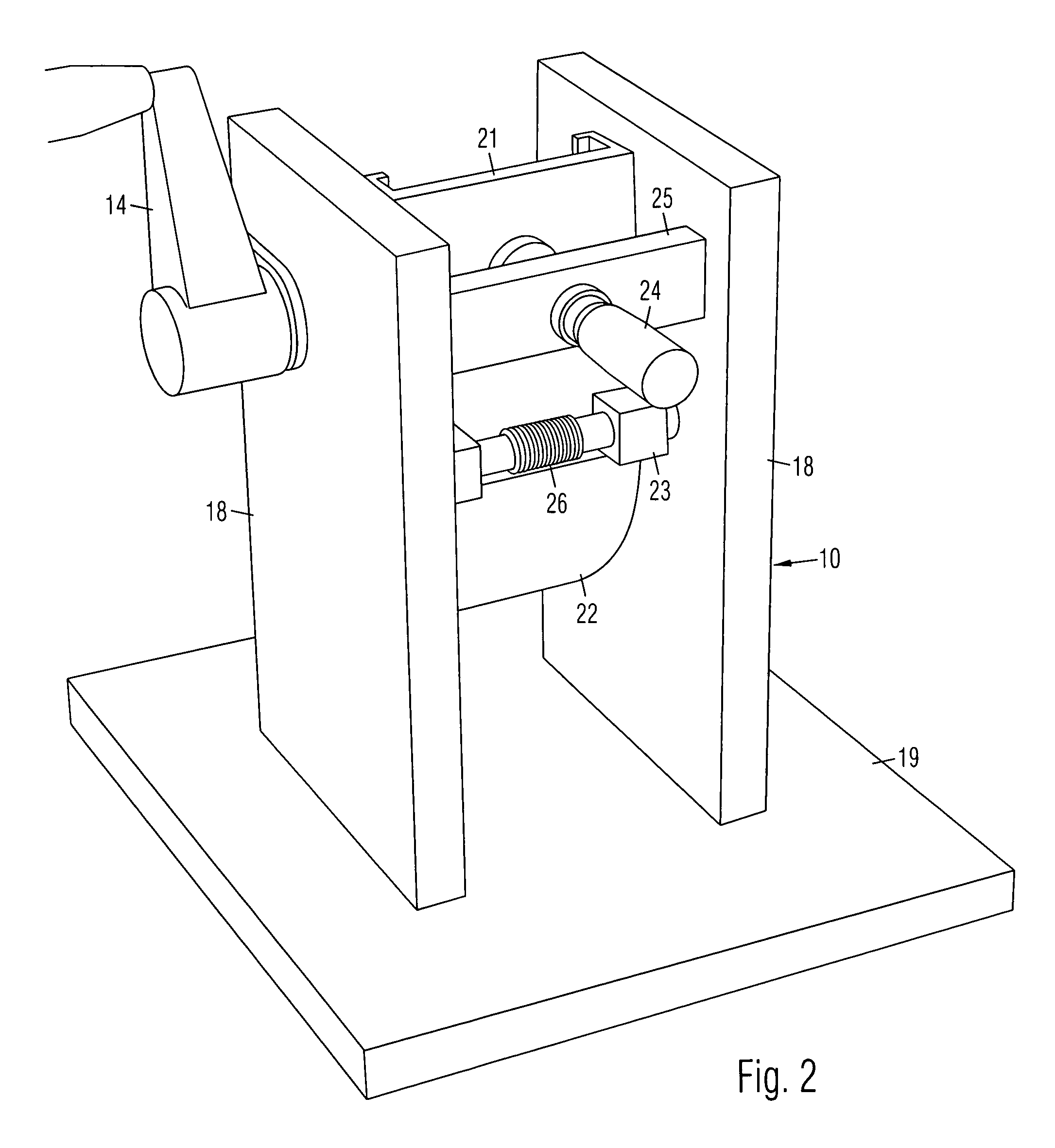
[0019]Shaft 12 is positioned between a pair of supporting walls 18 attached on a base 19. Bearings 13 are detachably received in bearing slots 20 in respective walls 18. A shield (not shown) may be provided between walls for covering blade. A guide member 21 is positioned behind blades 11. An output tray 22 ...


PUM

PropertyMeasurementUnit
Distanceaaaaaaaaaa

Abstract

A tissue slicing device is comprised of parallel circular blades coaxially connected to a rotary shaft. The blades are separated by gaps. A guide member is supported by a hinge adjacent the blades. An adjustment screw is positioned behind the guide member to control the distance between the guide member and the blades. The device includes a tissue carrier which is comprised of a base member and parallel plates extending from a top side of the base member. The plates are spaced to correspond with the gaps between the blades. Holes in the plates are aligned to define a tissue chamber for receiving a tissue sample. When the tissue carrier is positioned on the guide member and the blades rotated to drive the tissue carrier along the guide member, the tissue chamber is driven into the blades so the tissue sample is simultaneously cut into a plurality of slices.

Description

CROSS REFERENCE TO RELATED APPLICATIONS[0001]We claim the priority of provisional patent applications 60 / 561,113 filed on 9 Apr. 2004, and 60 / 635,118 filed on 11 Dec. 2004.BACKGROUND OF THE INVENTION[0002]1. Field of the Invention[0003]The invention broadly relates to biological tissue cutting devices.[0004]2. Prior Art[0005]Biological tissues for surgical pathology must be cut for chemical processing and embedding in paraffin. The cut tissues must be less than the inside dimensions of a standardized processing cassette which receives the tissues. The most commonly used tool is a hand tool such as a scalpel, knife, or razor blade, but it results in pieces with inconsistent dimensions. The thickness of the tissues directly affect the fixation rate in a fixative, the first step in the chemical processing. The quality of the fixation directly affects many of the downstream diagnostic tests. Therefore, tissue pieces with different thicknesses have different qualities of fixation that af...

Claims


Application Information

Patent Timeline
IPC IPC(8): B26D1/03B26D7/06
CPCB26D7/02B26D7/06G01N1/06B26D1/15B26D5/10B26D1/22Y10T83/741Y10T83/2216Y10T83/6577Y10T83/4734Y10T83/6608Y10T83/0348Y10T83/6668Y10T83/6588Y10T83/2218Y10T83/037Y10T83/654
Inventor GIBERSON, RICHARD T.HONAN, ROBERT L.
Owner GIBERSON RICHARD T
Why Eureka
Try Eureka