PSA pressure measurement and control system

a control system and pressure measurement technology, applied in the direction of chemistry apparatus and processes, separation of dispersed particles, separation of products, etc., can solve the problems of small breakthrough amount, drop in product recovery, and pollution of product on the next production stag

Active Publication Date: 2010-03-09
LUMMUS TECH INC
View PDF8 Cites 76 Cited by
  • Summary
  • Abstract
  • Description
  • Claims
  • Application Information

AI Technical Summary

Benefits of technology

[0038]FIG. 5 is a schematic diagram of a seven vessel PSA system depicting an advantage of the present invention; and
[0039]FIG. 6 is a schematic diagram of a hydrogen generator system depicting an advantage of the present invention.

Problems solved by technology

If the purge is insufficient, then the impurities desorbed during the depressurization stage are not swept out of the void space, consequently polluting the product on the next production stage.
However, if the purge is too great, then the volume of valuable product gas passed back through the vessel is in excess of that required to clean the void space of desorbed impurities at the desired purity level.
Over purge results in an undesirable drop in product recovery.
Although breakthrough of gas impurities during pressure equalization is undesirable, a small amount of breakthrough can happen during purge as pressure further decreases to achieve the desired purge-to-feed ratio.
The inventors have determined that his will result in one or several vessels in the system being out of balance with the others in terms of final axial composition through the vessel at the end of purge, potentially resulting in off-specification gas being sent to the product channel on the next production stage.
Comparing multi-vessel PSA systems that invoke, provide, and receive purge in the above manner shows several problems arise with this offset distance between vessels exchanging gas through the purge channel.
The inventors have determined that such systems will result in one or more vessels being out of balance with the others in terms of final axial composition through the vessel at the end of purge, potentially resulting in off-specification gas being sent to the product channel on the next production stage.

Method used


Image

  • PSA pressure measurement and control system
  • PSA pressure measurement and control system
  • PSA pressure measurement and control system

Examples


Embodiment Construction

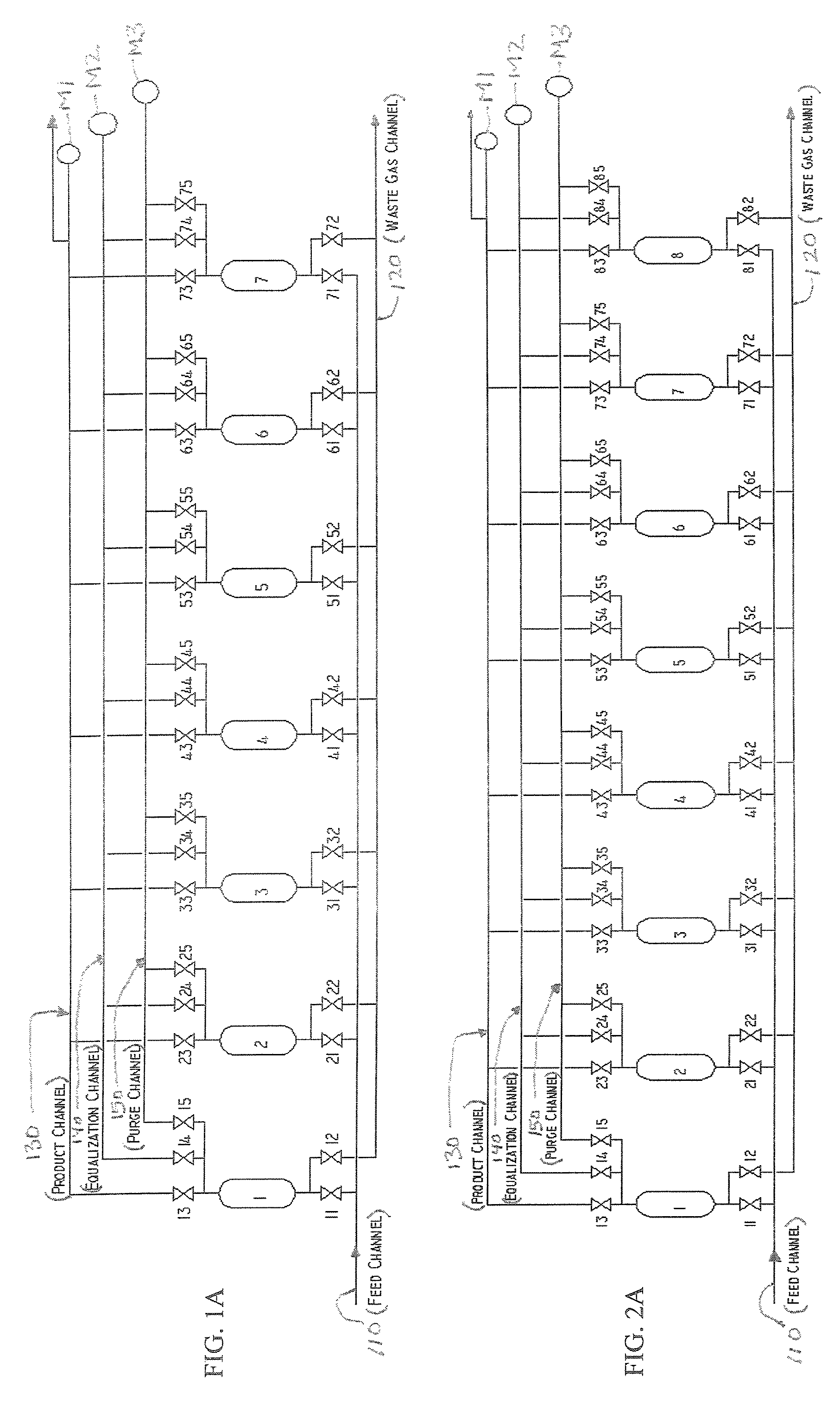
[0040]Embodiments of the present invention will be described hereinafter with reference to the accompanying drawings. In the following description, the constituent elements having substantially the same function and arrangement are denoted by the same reference numerals, and repetitive descriptions will be made only when necessary.

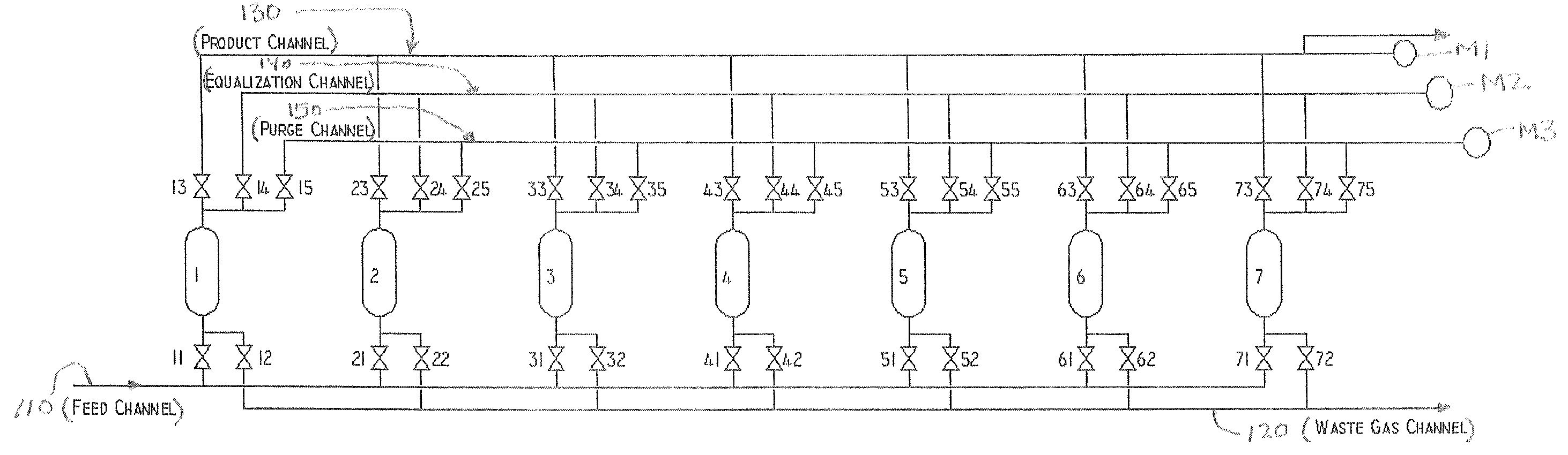
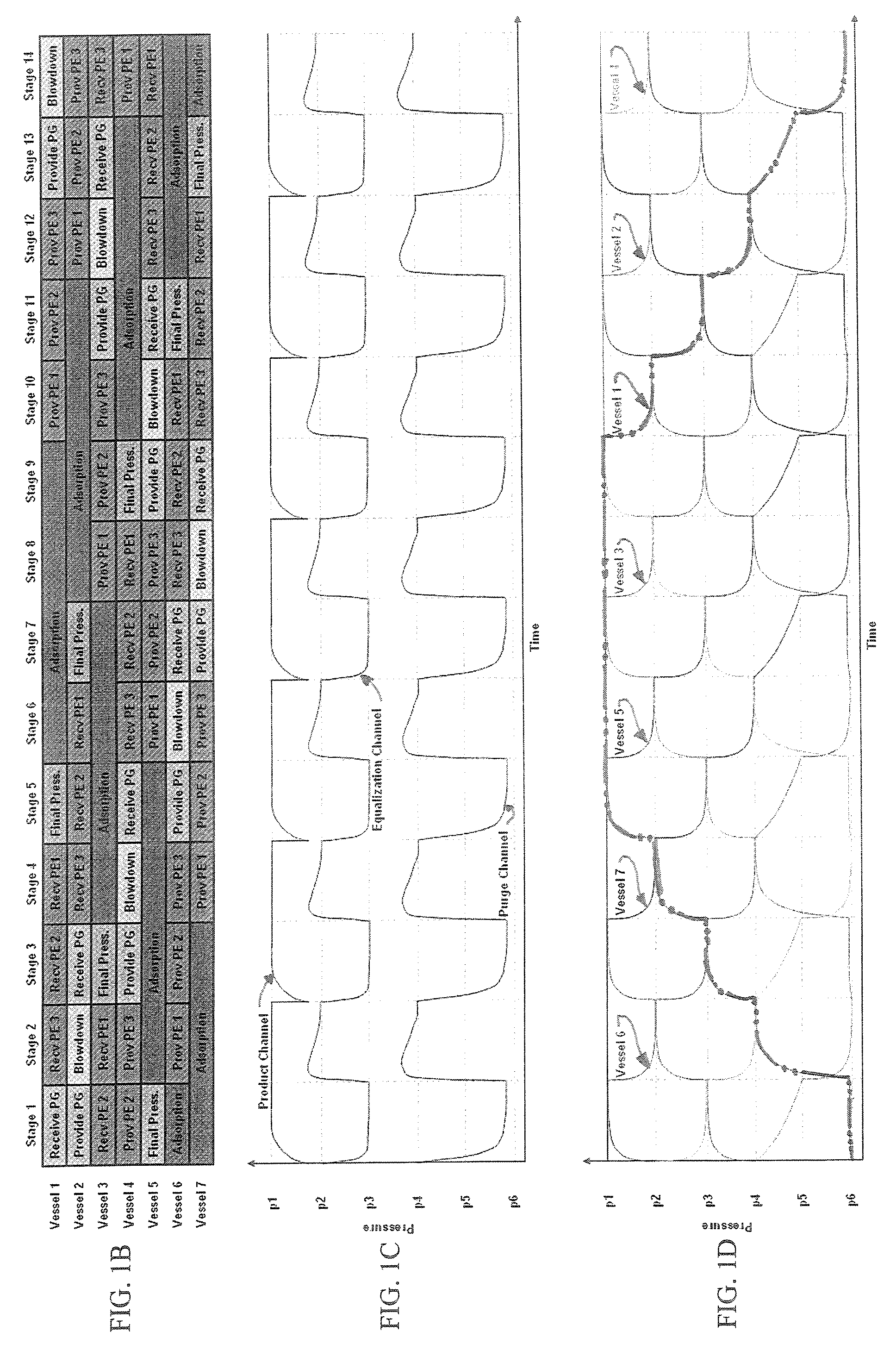
[0041]A first aspect of the present invention provides that, from a control standpoint, it is critical to verify that each stage of the cycle has been properly performed and that the correct sequencing of opening and closing on-off valves to the equalization, purge and product channels has occurred. In addition to verifying proper valve functioning during normal operation, accurate and real-time knowledge of the pressure in each of the vessels in the PSA system can be used to:

[0042]1.) Pre-fill the vessels with gas during startup;

[0043]2.) Depressurize the vessels to a pre-determined pressure at shutdown; and

[0044]3.) Verify leak-tightness of the PSA syste...


PUM

PropertyMeasurementUnit
temperatureaaaaaaaaaa
pressure measuringaaaaaaaaaa
pressureaaaaaaaaaa

Abstract

A pressure swing adsorption system including a plurality of vessels having one or more layers of adsorbent material therein, a feed gas channel, a waste channel, and a product channel. The system also includes at least one parallel channel connected to each of the vessels via a respective conduit with a valve. At least one pressure measuring device i configured to measure a pressure within the parallel channel. And, a controller is provided that is configured to monitor the at least one pressure measured by the at least one pressure measuring device during a PSA cycle performed within the PSA system, in order to determine the performance of the cycle and monitor proper operation of the system.

Description

CROSS-REFERENCE TO RELATED APPLICATION[0001]This application is related to the following application: U.S. Provisional Application Ser. No. 60 / 778,912, entitled “PSA Pressure Measurement and Control System,” filed on Mar. 6, 2006, which is incorporated herein by reference in its entirety.BACKGROUND OF THE INVENTION[0002]1. Field of the Invention[0003]The present invention generally relates to pressure swing adsorption systems. More specifically, the present invention relates to a monitoring and control system for pressure swing adsorption systems.[0004]2. Discussion of the Background[0005]Pressure swing adsorption (PSA) systems are used for the separation of one or more gases from a mixture of gases. A PSA apparatus usually includes multiple pressure vessels filled with a suitable adsorbent / adsorbents, with each vessel subsequently connected to two or more on-off valves that sequentially admit and expel gases at different pressures in order to affect the gas separation. The PSA cycl...

Claims


Application Information

Patent Timeline
Patent Type & Authority Patents(United States)
IPC IPC(8): B01D53/02
CPCB01D53/0446B01D53/047B01D53/053B01D2256/16B01D2259/40001B01D2259/40009B01D2259/40039B01D2259/40052B01D2259/40075B01D2259/406B01D2259/4063B01D2259/4066B01D2259/4067B01D2259/4145
Inventor LOMAX, JR., FRANKLIN D.VAN DYKE, CHRISTOPHER H.LEITCH, KELLY R.TODD, RICHARD S.
Owner LUMMUS TECH INC
Why Eureka
Try Eureka