
System and method for video transmission line fault detection

a video transmission line and fault detection technology, applied in the field of video circuits, can solve the problems of increasing the time needed for a technician to locate and troubleshoot such problems in video systems, and the complexity of video systems is becoming more complex, so as to prevent the false indication of faults

Active Publication Date: 2010-03-09
MAXIM INTEGRATED PROD INC
View PDF22 Cites 5 Cited by
  • Summary
  • Abstract
  • Description
  • Claims
  • Application Information

AI Technical Summary

Benefits of technology

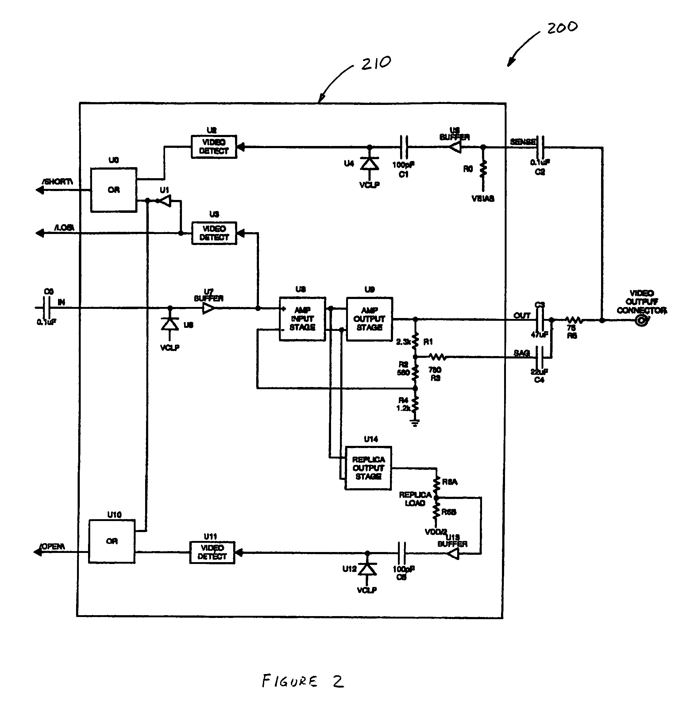
The invention is a video circuit that can detect short circuits and loads connected to the output of a video amplifier. It includes a short detection circuit, a load detection circuit, and an input signal detection circuit. The video circuit can also prevent false indications of faults when there is no input video signal. The short detection circuit includes a buffer amplifier, a sync tip clamp circuit, and a video signal detection circuit. The load detection circuit includes a replica output stage, a replica load, a sync tip clamp circuit, and a video signal detection circuit. The input signal detection circuit includes an edge detector, a capacitive element, and a pair of push-pull transistors or a clock and a counter. The technical effects of the invention are to improve the accuracy and reliability of video circuits by detecting and preventing short circuits and loads, and to enable the outputting of video signals even when there is no input video signal.

Problems solved by technology

Such video systems are also becoming more complex because more devices are connected together.
Because of the increasing complexity of video systems, it is now more difficult for a technician to locate and troubleshoot problems occurring in video systems, especially those having extensive routing of video transmission lines.
For example, the problem may lie in the video input circuitry, video output circuitry, or in the video transmission lines.
The time needed for a technician to locate and troubleshoot such problems in video systems is often long.
Accordingly, the labor cost of locating and troubleshooting problems is also likely to be relatively high.

Method used


Image

  • System and method for video transmission line fault detection
  • System and method for video transmission line fault detection
  • System and method for video transmission line fault detection

Examples


Embodiment Construction

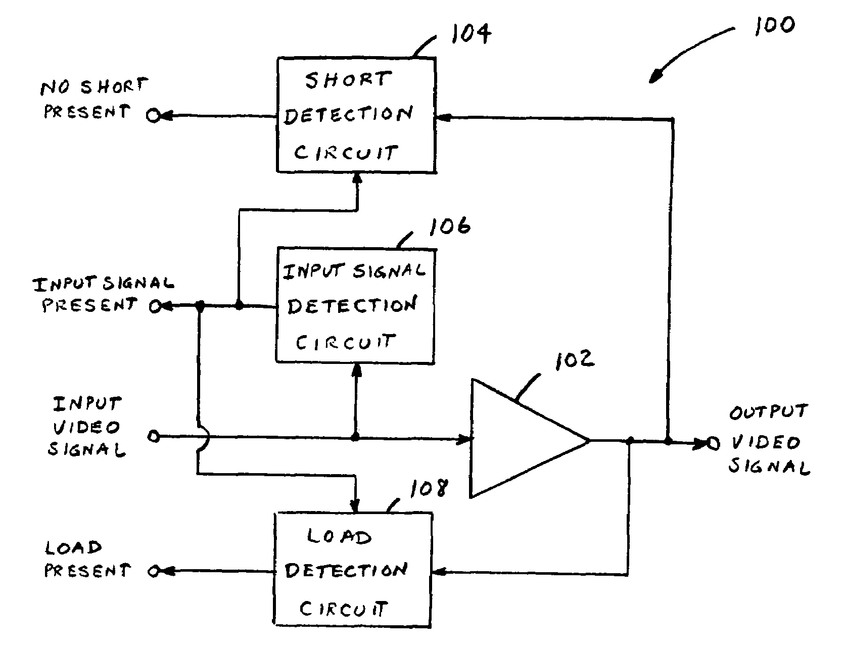
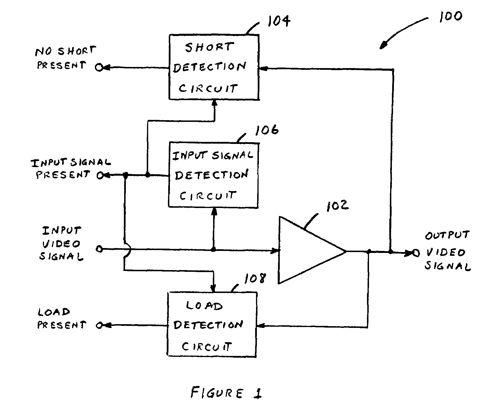
[0014]FIG. 1 illustrates a block diagram of an exemplary video circuit 100 with output fault detection in accordance with an embodiment of the invention. In summary, the video circuit 100, in addition to amplifying an input video signal, is capable of detecting faults that are present at its output. Such faults include the absence of a load connected to the output of the video circuit 100, and a short present at the output of the video circuit 100. Such faults may lie in the video transmission line connected to the output of the video circuit 100. The video circuit 100 also senses the presence of an input video signal and enables the outputs of the load and short detection circuits only when an input video signal is present to prevent false indication of faults when no input video signal is present.

[0015]More specifically, the video circuit 100 comprises a video amplifier 102, a short detection circuit 104, an input signal detection circuit 106, and a load detection circuit 108. The...


PUM

PropertyMeasurementUnit
threshold voltageaaaaaaaaaa
time delayaaaaaaaaaa
voltageaaaaaaaaaa

Abstract

A video circuit including a video amplifier adapted to generate an amplified output video signal from an input video signal; a short detection circuit adapted to generate a first signal indicative of whether there is a short present at an output of the video amplifier; and a load detection circuit adapted to generate a second signal indicative of whether there is a load coupled to the output of the video amplifier. The video circuit may further include an input signal detection circuit adapted to generate a third signal indicative of whether an input video signal is present. The third signal generated by the input signal detection circuit may be used to enable the outputting of the first and second signals in order to prevent the false indication of faults at the output of the video amplifier in the absence of an input video signal.

Description

FIELD OF THE INVENTION[0001]This invention relates generally to video circuits, and in particular, to a system and method for detecting faults affecting the output of a video circuit, such as those present in video transmission lines.BACKGROUND OF THE INVENTION[0002]Video is becoming more prevalent. Many automobiles and airplanes now have DVD players and TV tuners. In addition, casinos, hotels, and public areas have ever more surveillance cameras. Such video systems are also becoming more complex because more devices are connected together. Accordingly, the number of video transmission lines in such complex video systems has grown substantially.[0003]Because of the increasing complexity of video systems, it is now more difficult for a technician to locate and troubleshoot problems occurring in video systems, especially those having extensive routing of video transmission lines. In addressing problems in video systems, a technician has to first determine the source of the problem. Fo...

Claims


Application Information

Patent Timeline
Patent Type & Authority Patents(United States)
IPC IPC(8): H04N17/00G01N27/26G01R27/00G01R31/08H03F1/00
CPCH04N5/148H04N7/102H04N17/00H04N5/18
Inventor KOO, RONALD BONSHAWPETERSEN, MICHAEL DAVID
Owner MAXIM INTEGRATED PROD INC
Learn More