
Single Axis Accelerometer with Inertial Threshold

a single-axis accelerometer and threshold technology, applied in the direction of speed/acceleration/shock measurement, galvano-magnetic material selection, instruments, etc., can solve the problems of inability to port this technology to all vehicle platforms, inability to detect threshold acceleration or deceleration forces, and inability to adapt to all vehicle platforms

Active Publication Date: 2020-07-30
MECHOPTIX
View PDF0 Cites 0 Cited by
  • Summary
  • Abstract
  • Description
  • Claims
  • Application Information

AI Technical Summary

Benefits of technology

The present invention is a solution for detecting a threshold deceleration or negative acceleration in high vibration environments. It is achieved by using a single axis accelerometer with an inertial threshold comprising a swing arm that is constrained to swing in around a single axis. The swing arm is prevented from moving in response to acceleration forces in two directions having less than a threshold force. However, it will move to a position that activates a sensor to indicate that an acceleration force in excess of the threshold force has been experienced. This enables reliable detection of a threshold deceleration. The detection may be limited to accelerations sustained for a preset minimum duration to prevent detection of fleeting accelerations associated with travel over rough surfaces. The accelerometer may be constructed in a small size, low weight, and low power consumption when compared to many existing pendulum type accelerometers. Additionally, a spheroidal mass contained within a guide may be used for certain applications.

Problems solved by technology

However, attempts to port this technology to all vehicle platforms have been difficult.
No adequate solution exists for recreational and fishing boats, personal watercraft, snowmobiles, or bicycles, for example, in part because these vehicles exhibit motion dynamics and g-forces more intense than passenger vehicles on roadways.
While the aforementioned accelerometers provide useful acceleration detection for a wide variety of applications, none of these accelerometers are suitable for the detection of threshold acceleration or deceleration (negative acceleration) forces in vehicles experiencing motion dynamics and g-forces more intense than those typically experienced by trucks and passenger vehicles on roadways for the purpose of usefully indicating deceleration.
A number of the accelerometers are too large or too heavy for use with bicycles or require constant power at levels that prevent battery powered use.

Method used


Image

  • Single Axis Accelerometer with Inertial Threshold
  • Single Axis Accelerometer with Inertial Threshold
  • Single Axis Accelerometer with Inertial Threshold

Examples


Embodiment Construction

[0017]All art specific terms used herein are intended to have their art-accepted meanings in the context of the description unless otherwise indicated. All non art specific terms are intended to have their plain language meaning in the context of the description unless otherwise indicated.

[0018]As used herein, for a sensor to be engaged by a sensor trigger means that the trigger is in apposition to the sensor in a position to activate the sensor.

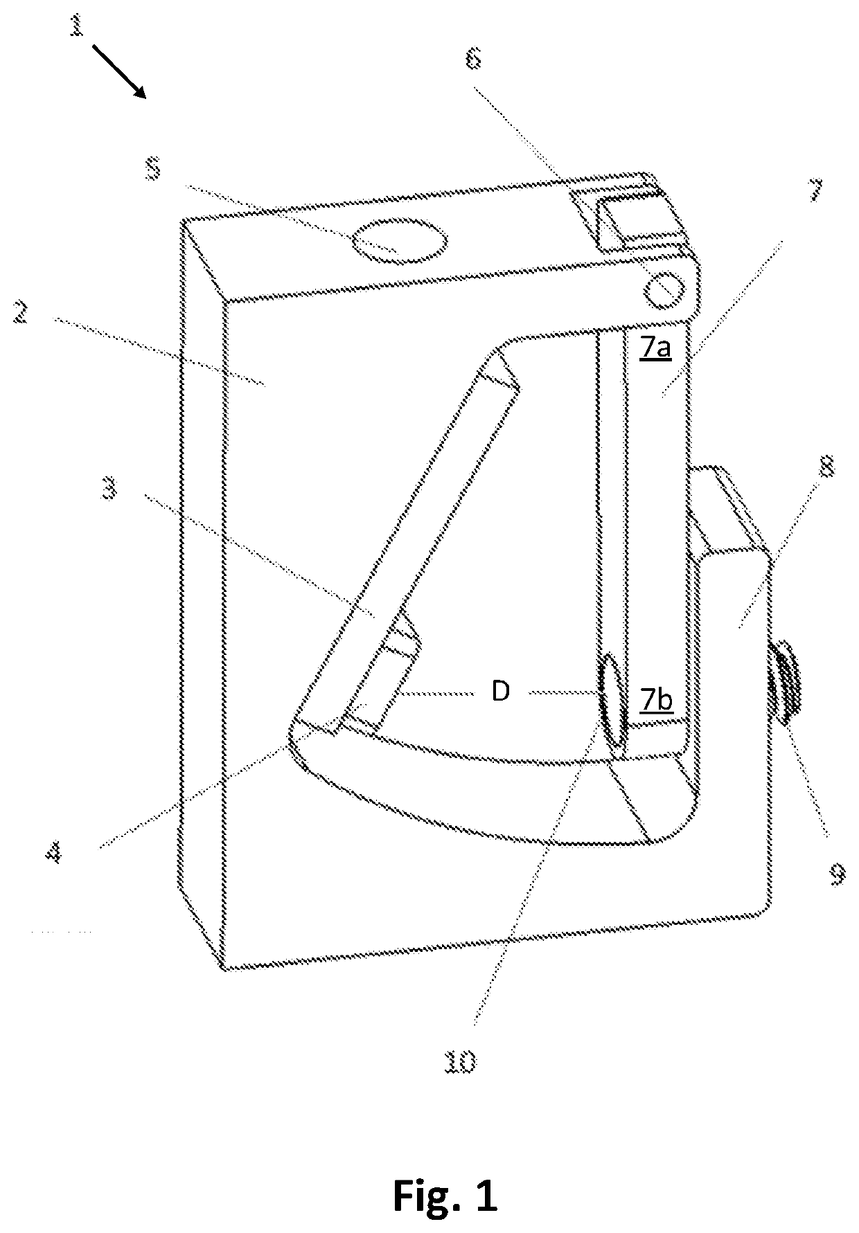
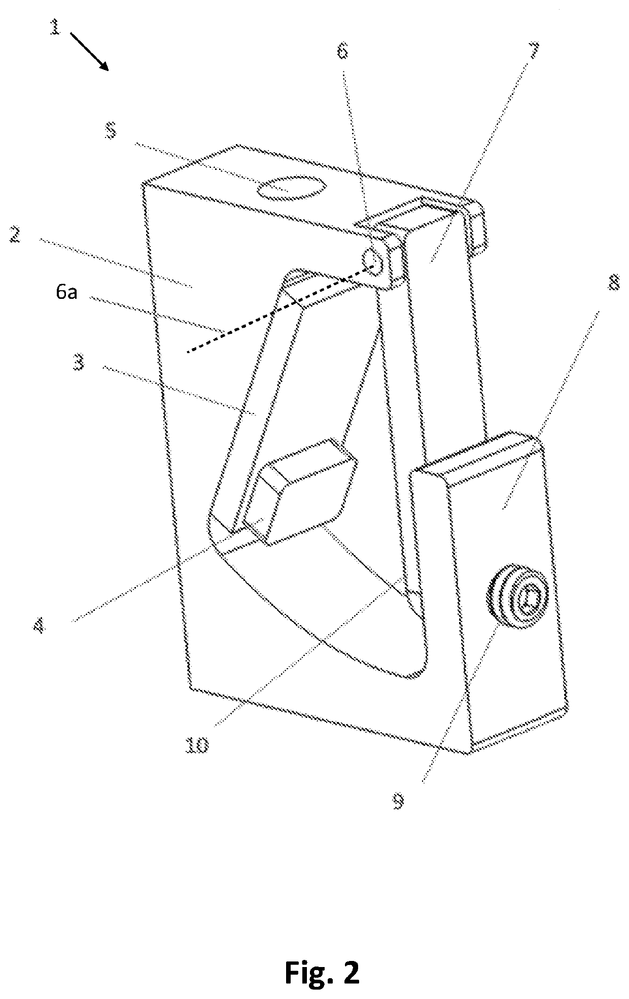
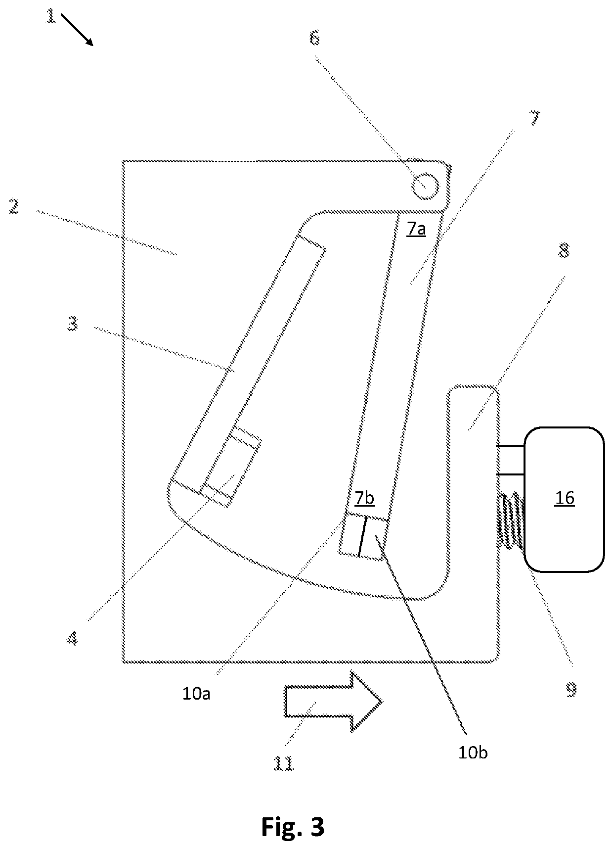
[0019]Embodiments of an accelerometer and methods of operation are shown in FIGS. 1-5 and used to explain technical features of the invention and their technical effects. The invention may be embodied as any number of variations of the embodiment shown in the figures and described herein.

[0020]FIGS. 1 and 2 show an exemplary embodiment of an accelerometer assembly (1) comprising a frame (2), a swing arm (7), a sensor (4), a printed circuit board (PCB) (3), a stop (8), and a threshold setting device (9). The frame (2) in this example is embod...


PUM


Abstract

A single axis accelerometer comprising a swing arm pivotally attached to a frame is held in apposition to a stop by a threshold force until an experienced acceleration force greater than the threshold force causes a distal segment of the swing arm to release from the stop and move toward a sensor that is activated by a sensor trigger on the distal segment of the swing arm.

Description

BACKGROUND OF THE INVENTIONField of the Invention[0001]The present invention relates generally to providing a single axis accelerometer for accurate acceleration / deceleration measurement with minimal influence from all other axes. More specifically, the invention relates to a single axis accelerometer having a threshold inertia that is optionally adjustable.Discussion of Related Art[0002]Automatic deceleration indication in automotive applications can be achieved by using a 3-axiss accelerometer to measure the force of the deceleration and illuminating a brake light if the measured force of deceleration exceeds a pre-determined threshold. Examples of inventions providing such indication are disclosed in U.S. Pat. No. 9,327,642 and US 2018 / 0009372. Vehicle motion due to rough road surfaces, inadequate or sport-tuned suspension, incline / decline angle, and lateral forces when turning can contribute forces to the measured deceleration force that must be filtered out in order to achieve ...

Claims


Application Information

Patent Timeline
Patent Type & Authority Applications(United States)
IPC IPC(8): G01P15/105G01P15/04G01P1/02H01L43/10H01L43/04H10N52/80
CPCG01P15/04H01L43/10G01P15/105H01L43/04G01P1/023G01P2015/0834G01P2015/0837G01P15/0891G01P15/093H10N52/80
Inventor MCGINTY, JOSEPHHAMMOCK, JEFFERY B
Owner MECHOPTIX
Learn More